Happy 2018!

Work on the SDR-2017 is continuing, though progress has been slow and fraught with frustration. It pains me to say this, but it's mainly due to that "black box" stuff that N2CQR warns about - Linux and Quisk are fighting with my sound devices. I'll get 'em whipped into shape, but in the meantime figured I'd share a project from a few years ago:
I've worked on enough old radios to where I can usually align the AM circuitry by-ear; I know where the local stations are on the dial and what to expect for sensitivity and selectivity. AM is fairly easy because, for the large part, you're adjusting for maximum smoke. FM is a little more tricky, though. Yeah, it's possible to align by ear, but I find it actually faster and easier to align the IF and discriminator stages with a sweep generator, RF probe and scope. But, my sweep generator was old, large and kind of a pain to use, so I built a small, stripped-down unit that didn't take up more bench space than the radio I was working on.

For those who may be new to the hobby, a sweep generator is an oscillator that repeatedly "drifts" from one frequency to another over a certain period of time, then abruptly "tunes" back to the frequency where it started. When used in conjunction with an oscilloscope and detector probe, it allows one to view the shape, or bandpass, of a tuned circuit. There are some great YouTube videos demonstrating the procedure, so rather than go into the procedure here, I'll focus on the circuit I threw together.
The heart of the circuit is a voltage-controlled-oscillator (VCO) based around Q4, that, at the center of it's control voltage range, runs at 10.7 MHz. The 555 Timer is configured as a sawtooth-wave generator that serves as a common timebase for the VCO and "X" axis of an oscilloscope (via buffer U1B); the gain of U1C determines the sweep width, or differential between the high and low frequencies of the generator, and U1D adds a bias voltage to the ramp to scale the signal to tune the oscillator as desired.
The circuitry around U1A, Q1 and Q2 is, I think, kind of cute. I wanted to be able to indicate, on the screen of the scope, where 10.7 MHz would be on the X-axis, and came up with the rather crude but effective thought that, if I paused the timebase for just a couple milliseconds at any given point, it would light the screen phosphors a little brighter than the others - in other words, create a "blip" on the screen. So, U1A is a comparator that, when the ramp waveform reaches a certain threshold (set by R2), stalls the ramp generator just enough to increase the intensity at that point. Unfortunately, it doesn't photograph well, but you can almost, kind of see it at the peak of the waveform in the picture below:

The picture above and the one at the top of the page show the frequency response curves of properly adjusted IF stages. This is done by applying the sweep generator signal at the input to the stage and monitoring the output with a simple, diode detector probe (connected to the scope's Y axis.) The stages are "tweaked" for maximum amplitude at the marker (blip) frequency (10.7 MHz.)
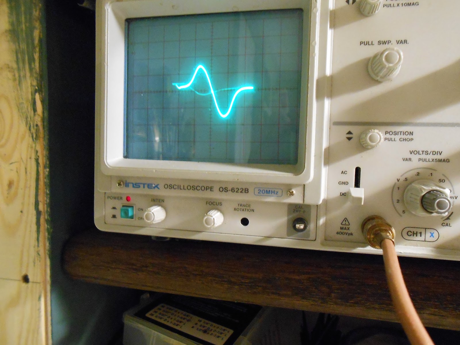
The next shot shows what's called the "S-Curve" response of a properly aligned discriminator (detector) stage. Again, the sweep generator is connected upstream, but this time the scope is connected, using a regular scope probe, to the output of the discriminator.
 Again, the marked didn't photograph well, but you can almost see it right in the middle of the "S". When the IF and discriminator are adjusted correctly, the positive and negative portions of the signal will be at their peak amplitudes, indicating that the IF's are adjusted for max. They'll also be of equal (but, obviously, opposite) amplitude with their zero-crossing point right at 10.7 MHz, indicating that the discriminator is in harmony with the IF passband. If you have the volume of the set turned up, it'll sound like a motorboat or a long, impressive fart, depending on how your mind works.

The finished product is shown above. The knobs are pretty self explanatory - marker is adjusted to put a "blip" right at 10.7 MHz, Width controls the difference between the lowest and highest frequencies of the oscillator (+/- a couple hundred KHz max) and level adjusts the output of the generator to suit the circuit under test. Even at it's minimum setting, it may be higher than needed for some measurements, hence the stack of in-line attenuators.
The enclosure is a from a defunct PC power supply; I stripped it of it's guts, made front and rear panels from #22 aluminum stock and sprayed it with some Rust-Oleum hammertone paint. Almost looks professional - close enough for me!
73 - Steve N8NM

Work on the SDR-2017 is continuing, though progress has been slow and fraught with frustration. It pains me to say this, but it's mainly due to that "black box" stuff that N2CQR warns about - Linux and Quisk are fighting with my sound devices. I'll get 'em whipped into shape, but in the meantime figured I'd share a project from a few years ago:
I've worked on enough old radios to where I can usually align the AM circuitry by-ear; I know where the local stations are on the dial and what to expect for sensitivity and selectivity. AM is fairly easy because, for the large part, you're adjusting for maximum smoke. FM is a little more tricky, though. Yeah, it's possible to align by ear, but I find it actually faster and easier to align the IF and discriminator stages with a sweep generator, RF probe and scope. But, my sweep generator was old, large and kind of a pain to use, so I built a small, stripped-down unit that didn't take up more bench space than the radio I was working on.

For those who may be new to the hobby, a sweep generator is an oscillator that repeatedly "drifts" from one frequency to another over a certain period of time, then abruptly "tunes" back to the frequency where it started. When used in conjunction with an oscilloscope and detector probe, it allows one to view the shape, or bandpass, of a tuned circuit. There are some great YouTube videos demonstrating the procedure, so rather than go into the procedure here, I'll focus on the circuit I threw together.
The heart of the circuit is a voltage-controlled-oscillator (VCO) based around Q4, that, at the center of it's control voltage range, runs at 10.7 MHz. The 555 Timer is configured as a sawtooth-wave generator that serves as a common timebase for the VCO and "X" axis of an oscilloscope (via buffer U1B); the gain of U1C determines the sweep width, or differential between the high and low frequencies of the generator, and U1D adds a bias voltage to the ramp to scale the signal to tune the oscillator as desired.
The circuitry around U1A, Q1 and Q2 is, I think, kind of cute. I wanted to be able to indicate, on the screen of the scope, where 10.7 MHz would be on the X-axis, and came up with the rather crude but effective thought that, if I paused the timebase for just a couple milliseconds at any given point, it would light the screen phosphors a little brighter than the others - in other words, create a "blip" on the screen. So, U1A is a comparator that, when the ramp waveform reaches a certain threshold (set by R2), stalls the ramp generator just enough to increase the intensity at that point. Unfortunately, it doesn't photograph well, but you can almost, kind of see it at the peak of the waveform in the picture below:

The picture above and the one at the top of the page show the frequency response curves of properly adjusted IF stages. This is done by applying the sweep generator signal at the input to the stage and monitoring the output with a simple, diode detector probe (connected to the scope's Y axis.) The stages are "tweaked" for maximum amplitude at the marker (blip) frequency (10.7 MHz.)
The next shot shows what's called the "S-Curve" response of a properly aligned discriminator (detector) stage. Again, the sweep generator is connected upstream, but this time the scope is connected, using a regular scope probe, to the output of the discriminator.

The finished product is shown above. The knobs are pretty self explanatory - marker is adjusted to put a "blip" right at 10.7 MHz, Width controls the difference between the lowest and highest frequencies of the oscillator (+/- a couple hundred KHz max) and level adjusts the output of the generator to suit the circuit under test. Even at it's minimum setting, it may be higher than needed for some measurements, hence the stack of in-line attenuators.
The enclosure is a from a defunct PC power supply; I stripped it of it's guts, made front and rear panels from #22 aluminum stock and sprayed it with some Rust-Oleum hammertone paint. Almost looks professional - close enough for me!
73 - Steve N8NM
No comments:
Post a Comment