Sunday, November 20, 2016

Ebay 45W linear amplifier - Heat sink & Bracket

Some pics of the heat sink and bracket that I'll be using during testing.  The heat sink came from a junk PC, and the bracket is bent from 26 gauge copper sheet.

Heat sink and bracket, drilled and tapped.

Bracket mounted to heat sink.

Test fit.

Of course, something always goes sideways when working on any project.  In this case, I planned to use an existing hole in the heat sink (already drilled and tapped) for mounting the 2SC1971 driver, but neglected to measure it first.  As luck would have it, it's too large, so I'll have to fill it with JB Weld, redrill and tap.  That's a project for another day.  


Saturday, November 19, 2016

Chinese "EBAY" 45 Watt linear amplifier "kit"


Looking to add a few dB to the QRP output of my HB rigs, I stumbled across a number of these Chinese Irf530 amplifiers on Ebay at very reasonable prices - generally $15, including shipping.  Not being one to pass up a potential bargain, I popped for one and it arrived today.  Above shows the contents of the package emptied into one of the XYL's best cake tins.  She'll never miss it.   Why a cake pan when I have a nice, white, melamine surface?  Because these parts are small and have an annoying tendency to pop free from the tweezers or forceps at the worst possible time, and a cake tin works perfectly to constrain those parts that attempt to go rogue.

Because the parts are so small and my eyes are not a sharp as they once were, I made use of the camera in my tablet to help identify the various resistors:

While it may be difficult to see here, I was able to clearly read the lettering on the part during assembly.

It's worth noting that there are a couple of different versions of this kit in circulation (v303 and v306), and the documentation provided (for download) from the vendors suffers from poor translation.  An improved english manual is available for v303, but it proved of limited value because, while the kits are very similar, there are some significant differences in both the design and parts used.  Best to suffer aong with the Chinglish instructions - which is really nothing more than a parts list (in .xls format), pictures of the top and bottom of the board, and instructions (again in Chinglish) for winding the three transformers and RF-choke.  These were adequate - I was able to understand what they were saying, but I'm at leat an intermediate-level builder and have wound countless ferrite transformers and chokes.  Still, it's hardly rocket science.

So, in constructing the board, I follow a practice of installing the small SMD parts first - it's easier to do so now than after adding larger parts that take the board from the 2nd to 3rd dimension. With this one, I started with the .01 capacitors, then the .1 and then the couple of 100 pF caps.  The large electrolytic and mica can wait.

After installing the caps, I moved on into the realm of resistance, soldering all the SMD resistors to the board.

It should be noted that, while the capacitor values are unmarked, when you inventory the parts, it'll be apparent which are which based on the quatities included with the kit.  The resistors ARE marked - not long ago, I could read the markings with the naked eye, but over the past 10 years, this has become challenging and I've had to resort to magnification.

Once the SMD stuff is installed, you can move on to the larger parts.  Easiest was to first install the two pots, and, while you're at it, set the center terminal of each to the ground side.  This way, the '530s will be turned-off when you fire it up, reducing the chances of accidentally frapping the silicon.

After this, I installed the two molded chokes and the 2 large 22 Ohm resistors, leaving enough wiggle room in the lead to solder in the '530s when the time comes.

I wound the transformers next.  The instruction sheets (downloaded) caution that the edges of the cores are sharp and should be relieved to prevent nicking the wire's insulation.  They mention scraping the edges with needlenose pliers, but I find it easier to chamfer the edges uing various sizes of phillips screwdrivers.

There's nothing tricky about winding these - a single winding is nothing more than passing the wire through both holes in the binocular cores, so do what it says and you'll be fine.  T3 has a tapped primary - put two one-turn windings through the core, twist the opposite ends of each winding togeter to form the center tap.  Not a big deal.

I still need to prepare my heat sink, so I left the board at this point before knocking-off for the night:
It took only a couple of hours to get to this point, and I've probably got about that much left in prepping the heat-sink, wiring up the power supply, low-pass filter and T/R relay.  With any luck, I'll be able to bang that out tomorrow and get on with some testing!  Wish me luck.

73 - Steve

Friday, November 18, 2016

"Broadbanded" 40 meter vertical antenna

Can you spot the antenna?  Of course YOU can, but it's proven relatively invisible to the typical non-radio cuckoo person thanks to a can of camouflage paint (Rust-Oleum "Deep Forest") from Lowe's.

There's nothing remarkable about the antenna itself, it's just 40' worth of aluminum sections mounted to a treated 4x4.  The sections telescope into one another, allowing the length of the antenna to be adjusted to bring it into resonance.  Very simple, but, no vertical will perform worth beans without a decent ground system.  Again, mine is nothing special: just a bunch of radials, between 30 and 100' long, buried just under the sod.  It's been several years since I installed this antenna and I don't remember exactly how many, but it's somewhere around 20...  I had a bunch of partial spools of wire and just kept burying them until I ran out :-)

Here's the cool part: On the lower frequencies, it's tricky to make a single antenna present a decent match across the entire band without some kind of tuner. A long time ago, someone showed me a simple way to "stretch" the bandwidth of an antenna by adding an electrical 1/4 wave section of 75 Ohm line to the base. So, at the feedpoint of this antenna is an electrical 1/4 wave section of RG-11, which connects to an electrical 1/2 wave section of RG-8 that feeds a bandpass filter located in a weatherproof box at the base of my tower, where it joins the section of RG-8 that runs through the underground conduits (about 150') and into the shack.

A brief description of how I understand it to work is: At resonance, the inductance (L) and capacitance (C) of the antenna and feed system are equal.  As you tune in frequency away from resonance, the L and C of the antenna and feed system change in opposite directions, countering each other; As the antenna "goes capacitive", the feed system "goes inductive".  Obviously, there are limits, otherwise the thing would look like 50 Ohms across the spectrum, but in this case, it's enough to provide a decent SWR across the band.

It's a simple trick that doesn't add appreciable cost or complexity to the system, give it a try!

Base of antenna - lag bolted to 4x4

View looking up from eye leve

Monday, November 14, 2016

NC-109: The final chapter.

Since the last post, I was able to "tweak" the Pullen Mixer circuit enough so that the radio works reasonably well, so I'll leave it in place as a tribute to W8NYI, the fellow who I believe perfomed the modification.

When I say "reasonably well", the radio now aligns properly - the dial tracks the oscillator and RF amp perfectly, but the RF gain seems down a bit, probably due to the difference in conversion gain between the two mixers.  Nevertheless, the sensitivity is totally adequate for shortwave.

So, the old girl is cleaned-up, tuned-up and, as shown at the top right of the above picture, happily among friends.

Oh, one interesting thing that I meant to talk about the other day - this set has seen a LOT of use: Check out the wear on the dial string "pulleys":


These pulleys don't turn (not meant to), the cord is meant to slide in the somewhat polished surface. In this case, it actually started to saw it's way through the copper!  Fortunately, an easy work-around was to simply restring the cords (one main, one bandspread) to use the unused half of each pulley, which works just fine.


So, another project added to the "done pile".  I've got a couple of ideas for what to take-on next, but first, I really need to clean the shop/shack... it's gotten completely out of hand :-)

73 - Steve N8NM

Saturday, November 12, 2016

NC-109: Day 3 and archeology

Thanks to my favorite chassis cleaning product, aptly named "Super Clean", I was able to get the chassis looking respectable in less than an hour.
I saw someone recommend this stuff, available at AutoZone, on one of the old-radio forums, and it works better for removing old nicotine residue than anything else I've tried - literally, spray it on and wipe it off.  Awesome stuff!

Here's what it looks like after a quick spritz and wipe.  Amazing!

The finished product:  Came out pretty nice, little corrosion toward the rear, but much better than before.

Under the chassis, I cleaned-up the wiring around the modified mixer stage (more on this later), replaced the few tubular paper caps and the mica wafer inside of Z2 (dreaded silver migration disease).  
Above is a shot of the underside of the mixer after all cleaning-up all of the flying leads.  Unfortunately, that all may have to go!  When I started alignment, I found that, no matter what, I can't get the dial to track properly across any of the bands, and this seems to be due to interaction between the RF and LO inputs of the mixer - there's not enough isolation, and the alignment of the RF side is affecting the LO frequency - probably why the AM band was inop.  So, unless I can correct this, I may remove the Pullen circuit and put everything back to it's original spec.  

Now, for the archeology part:  I forgot to take a picture while I had the front panel off, but penciled onto the chassis behind the panel is the callsign of, presumably, one of the previous owners: W8NYI.  I looked through back editions of the Callbook (scans are at archive.org) and found that W8NYI was Richard Smith, who lived on Prairie Street in Detroit - which was surprising, because I live in the Detroit area and purchased the rig in Eastern Ohio... So, the rig has come back home!


Unfortunately, the last Callbook in which W8NYI appears is 1975, so it's quite possible that he became a silent key. Since the 6DJ8 tube used in the mixer dates the modification to the late 60s/early 70s, I envison OM Richard toiling over it in the shack of his QTH in the old house (now gone) on Prairie Street.  This is why I'm reluctant to remove the modification - It's part of the rig's history and W8NYI's legacy; I sure hope I'm able to get it to work!

Wednesday, November 9, 2016

NC-109 Day 2


A couple hours into the NC-109 and it's starting to show.  Sometimes, it's surprising how much difference just a little cleaning-up can make - this thing is filthy!  Fortunately, the ancient nicotine and goo isn't putting up too much of a fight.

Electronically, I haven't run into any major problems, but did find a surprise - more on that later.

Initially, the "A" (AM Broadcast) band was dead, and in troubleshooting, I fell victim to the habit of "overthinking" the problem.  Initially, I suspected a defective component - dirty switch contact, open oscillator coil, or something along those lines, so I spent quite a bit of time checking components.  When I measured the L and C in the oscillator circuit, I discovered that the inductor was out of range and the problem was simply alignment.  I didn't expect that to be an issue because the rest of the bands were dead-nuts on, but the "A" band coil had just been screwed down a few turns too many.  Easy fix!

In the process of troubleshooting that problem, though, is where I found the surprise: A previous owner had extensively modified the mixer - the original 6BE6 had been replaced by a 6DJ8.  That number didn't ring a bell, so I looked it up and found it to be a dual-triode.  A-HA! I quickly drew the circuit as it was installed, and confirmed the circuit as being the "Keats Pullen" mixer that I've used in some of my homebrew projects:
Since I know that this circuit can work quite well - and it seems to be in this rig - I think I'm just going to clean up the workmanship.  As you can see below, it's a little haywired:

Another modification that had been done - and I un-did - was installation of a 50uF cathode bypass on the audio PA.  According the the schematic in the manual, the cathode is unbypassed, and it was pretty obvious that the capacitor wasn't installed by the factory.  I imagine that the intent was to juice up the gain of the stage, and that it did, but it significantly increased the residual hum, especially when using headphones.  The stage has plenty of gain and sounds great without it, so: Bye bye.

Otherwise, I cleaned the switches and controls, and cleaned/lubricated the bearings in the tuning caps, which were quite stiff.  I may have to give some attention to the dial cords as well; the springs are stretched (probably from cranking the stiff caps) and the bandspread slips.  Fortunately, the stringing scheme is pretty simple, so this isn't as big a deal as it could be.

That's all for tonight!


Sunday, November 6, 2016

Something Different - National NC-109


 I need another old SW receiver like I need another hole in my head, but I felt sorry for this old NC-109 when it came up at an auction I attended last summer and nobody wanted to bid on it.  I don't remember what I ended up giving for it, but it wasn't much.

Other than being dirty, it appears to be all there, so let's see what we have:


 Typical dusty, dirty chassis - looks like a layer of nicotine residue, but no rust or mouse damage, and all the tubes are there.  We're off to a good start!


This is interesting.  At the top of the chassis, it looks like someone hacked-in a 40uF electrolytic and 500 ohm wirewound, probably because the multi-section filter cap wasn't doing it's job. Sigh. Kids.  

That was an easy fix, though, and what's cool is that there aren't many tubular paper caps to deal with - National used ceramics for bypassing, and those don't usually fail.

Normally, I like to remove and restuff chassis-mounted electrolytics, but I really don't feel like this rig is worth the effort.  I might change my mind tomorrow, but for now, I've disconnected the can and installed new caps on a terminal strip.


Now for the fun part!  After changing the filters and inspecting for any other obvious problems - time to power it up!  I don't have any pics of this process (not much to see, really) - I use a variac connected to an isolation transformer, and bring it up slowly, watching for any signs of trouble.  This old National fired right up - no magic smoke was released!  Yippee!

At this point, I gave it a quick evaluation, starting a "punch list" of things still needing attention:
  1. Band 1 (AM BC) is dead.
  2. Strange AVC "pumping" and background noise - mixer?
  3. Dirty controls/switches.
  4. Main tuning and Bandspread caps stiff - need clean/lube.
  5. Rudimentary cosmetics / degrunge.
  6. Screw terminals for antenna disconnected/rerouted to added SO-239 - need to be restored (why do people do this?)
Nothing looks too bad.  On the good side: 
  • It receives: Envelope and product detectors are both working.
  • ANL works.
  • BFO works.
  • Crystal filter/selectivity switch works.
  • Dial calibration is reasonably close.
  • Only a handful of tubular paper caps and one LV electrolytic (AF cathode bypass) to replace.
  • Nothings smoking!
So, barring anything unforeseen, should be able to whack this one out in a few nights.  Wish me luck!!!

73 - Steve

It's shiny...

The new audio board and isolation transformers (shown above) have been installed and working exactly as I'd intended; to quote Hannibal from the A-Team: I love it when a plan comes together!

Operationally, there are two input channels for transmit audio: The microphone and CW sidetone on one, and the soundcard interface on the other.  This separates the audio paths, allowing the level of each to be optimized without affecting the other. Also, as I mentioned in my last post, it mutes the microphone audio during digital transmissions, preventing any unintended voice transmissions while operating the digital modes.

I have had intermittent problems with hum on receive and/or transmit due to ground loops.  Mounting a bunch of modules to a chunk of wood is nice for experimenting, but it's not necessarily the ideal platform when it comes to ensuring no differences in ground potential exist between the circuits.  I'd tried a number of "easy fixes", none of which ended up being particularly easy or fixing the problem, so I finally said "screw it", pulled everything off the board, laid down a sheet of copper, and remounted everything.  This seems to have all but eliminated the problem, and has the added benefit of being shiny - at least for now.


So, for all intents, I'm calling this one "done".  Over the past few weeks, I've made dozens of QSOs on CW, SSB and JT65/JT9, where, just a few minutes ago I was able to "cross the pond" for the first time, working PB8DX in The Netherlands.  Even after all these years, it still amazes me to think that a bunch of parts on a piece of wood, connected to some wire hanging from a tree branch, can be used to talk to someone 4000 miles away.  Wild!

73! Steve N8NM


Saturday, October 29, 2016

A NEW Audio Board for The Planker


After some discussions with a fellow named Francis Flynn on Facebook about better ways to mute the RX audo during TX, and then subsequently looking at my original design and trying to come up with a better way to implement CW and Digital Modes (I'm diggin' JT65!), I decided to scrap the thing and start over.  It took a few days, but I installed the board diagrammed above in the rig today and it's working great!

As I mentioned in the post from earlier this week, my Linux PC does not have a serial port to support PTT, and I had no luck using a USB dongle, so I'd built a simple VOX circuit to provide T/R control when operating digital modes.  This worked well (I kept the VOX board), but, since the microphone and soundcard audio used the same amp, I had to remember to unplug the mic when operating digital, else my digital tones would be accompanied with my occasional bursts of unsavory language "What the F*&^ is this A$$ H01E doing!??"  Obviously the FCC frowns on that sort of thing, and lacking self control, I felt that addressing it through technology was the prudent course of action.

So - This board, well, to me, it's simpler:  The Audio PA uses the same LM380 as the original board, but the 2N3904 preamp has been replaced by one section of an TL082 Op-Amp (I know, the schematic says LM324 - it's pin compatible..)  This amp and the '380 are powered in both RX and TX modes, as they are necessary to provide an audible CW sidetone.  However, the 4066 CMOS gate at its input disconnects it from the product detector/balanced modulator while in transmit.

The microphone audio and digital audio sources each have their own TL084 amps, and the gain of each is optimized for the two applications.  The remaining three gates of the 4066 are configured to, when the microphone PTT initiates transmit, gate mic audio to the balanced modulator, and, when the Digital Vox is active (low) the microphone is switched out of the circuit and digital audio gets routed to the modulator.

Not shown is the CW sidetone interface (forgot to document it...) - The local audio (speaker) is injected at the "hot" side of the volume control, while the audio to be transmitted is sent directly to the microphone amplifier.  In this case, one still must be congniscent of speaking while sending CW - the mic will be live - but I don't worry about that as I seldom say anything while talking with my hands.

I'm pretty happy with the performance of this board: Microphone and digital audio sound perfect, while CW still needs a bit of work as it is only driving the rig to 3-4 watts.  This should be an easy fix - The CW filter module terminates in an attenuator network, so I just need to pare back a few dB worth of attenuation.  Souldn't be a big deal.

Anyway, Thanks Francis Flynn!  Your comments got the grey matter stimulated, and this board is a definite improvement over the original.  Also, thanks for sending the link to the W7EL rig - That was a nice walk down memory lane, and seeing how Roy used the FET as a mute gate gave me the idea to use the 4066 CMOS chips for audio switching and routing.  FB OM!!

73 and go make something!!!

Steve N8NM

Monday, October 24, 2016

Planker Circuit Description: Audio Module

I'm cleaning up some of the Planker docs in preparation for an article for QRP Quarterly, and will pop them up here with brief descriptions and notes.  Since I like to start every project from the "back end", I'll start here with the audio board.

Planker audio board Rev 1.0
This board is fairly straightforward: On the left side is the transmit audio circuit, starting with  the mic connector,followed by a two-stage mic amp using a J310 and 2n3904.  

Toward the center, you'll see the common connection to the Product Detector/Balanced Modulator board, to the right of which is a 2N3904 amp driving an LM380-8.  To produce an audible CW sidetone in the speaker/phones, the output from the sidetone circuit is introduced at the top of the AF Gain pot. The LM380 is powered on in both transmit and receive, but power to the driver transistor is disconnected while in transmit.  Nonetheless, enough voice audio leaked through to the 380 that it was clearly audible, so I added a 2N7000 to shunt the output from the driver to ground while transmitting. Even though this places the 1uF at the top of the volume control at ground potential, enough sidetone still get's throug to be useful, and I see no reason to improve on it.

The circuit above delivers enough mic audio (using a cheap condensor) to drive the rig to full output, and the coupling caps were chosen to minimize low-frequency response.  All stations worked so far have made positive comments about the audio, so I'm calling that a success!

The receive audio will easily deliver a couple of watts to an 8 Ohm speaker, and is pleasant to listen to.

The next board that I plan to document is an adjunct to this one, providing separate inputs for a computer soundcard interface for digital modes, and a functional VOX circuit.  Maybe I'll have that up tomorrow, maybe not... We set goals, not deadlines!

73- Steve N8NM 

Saturday, October 22, 2016

The Planker goes digital.

I'm finding CW and SSB activity on 60m is pretty limited, but "channel 3" is hopping with JT65 signals throughout the evening.  So, what the heck - might as well jump in!

Running WSJT-X on my Linux laptop, I ran into a challenge in getting the rig to transmit:  The laptop doesn't have a serial port, and it recognizes my USB<>serial dongle as ACM0.  Unfortunately, WSJT-X only supports Sn and USBn devices, and while I'm sure there's a symlink work around, it was simply easier for me to deal with it in hardware by adding a simple VOX circuit.  So, I kludged one together and made my first JT65 QSO!

This is going to lead to a redesign of the RX/TX audio board, not only to incorporate VOX, but to provide separate RX & TX audio I/O (with isolation transformers) for the PC interface. I'd planned on redesigning the board anyway, there are a few things on the current board that I'm not entirely happy with, so it's not a big deal.  I'll put up the diagram and some pics once I have it operational.

73!  Steve N8NM 

Saturday, October 15, 2016

On the air with The Planker!


After a few months of casually melting solder, The Planker made it's maiden voyage yesterday afternoon when I enjoyed a brief chat with Lauren, WD5HIO, in central Ohio.  I'm very pleased to say that nothing exploded or otherwise malfunctioned, and Lauren commented that I had a very nice signal with "excellent audio".  Yes!!!!

So, what is all this Planker nonsense?  It stems from an email exchange I had with Pete, N6QW, earlier this summer.  Pete had been working on a rig covering 40 and 60m, 60 being the only amateur HF band that I'd never operated on.  At that time, I was putting the finshing touches on my "all-band" HF rig, and was getting a little frustrated because I'd built myself into a corner and was running out of space on the chassis.

Since I'd never been on 60, I became intrigued by Pete's rig, and thought that it'd be a good "rainy day" project for the summer if I kept it simple enough.  At the same time, I wanted to avoid my bad habit of establishing a "form factor" for the chassis and trying to fit all of the circuitry within those confines, and, since I've had this 24" chunk of pine board kicking around for years, everything just clicked.  As N2CQR says: TRGHS - The Radio Gods Have Spoken.

The architecture of the rig is very similar to Farhan's (VU2ESE) BITX: It's a single-conversion superhet SSB transceiver using bilateral IF stages.

Each individual stage is built as a module, the input and output impedance of which is 50 Ohms.

 From left to right: The small board is a 7 pole LPF, behind which is the power amplifier (based on Farhan's RF386) and forward of which is the antenna relay and pre-mixer bilateral amplifier (based on W7ZOI's "TIA" circuit, using six 2N3904s.)

Moving to the back of the plank, the two upright transistors to the right of the PA handle the T/R switching.  These are actually some bogus 2SC1969s that I bought on Ebay; they don't work at RF, but are adequate DC switches.

In front of the switch board is the mixer, a homebrew DBM using "matched" 1N4148 diodes.  Forward of the mixer is the 20 MHz IF amplifier, another W7ZOI "TIA" module.

Underneath the crooked shield (right of the switch/mixer/IF amps) is the crystal filter, which I made from seven 20MHz CPU crystals.  The bandwidth of the filter was set, largely experimentally, to 2.4 KHz, by selecting the appropriate shunt capacitors.  I first modeled it on the computer and then adjusted it using a spectrum analyzer.

Moving to the right again, what you can't see (because it's behind the display panel) is the product detector/balanced modulator, which is the 2 diode single-balanced circuit stolen from the BITX.

The display panel is, well, a display panel... A small board behind the 7 segment display contains the 4511 driver IC, and the pushbutton steps through the five 60m channels and WWV at 5 MHz.

The next board is the synthesizer and MCU.  I'm using an Arduino Pro-Mini to control a SI-5351, which provides the local and beat frequency signal sources.  And no, phase noise isn't an issue.

Then, finally (if you've made it this far) is the transmit and receive audio board.  The transmit audio amplifier is a pair of cascaded JFETS (J310), and the receive side uses a 2N3904 to drive an LM380-8.

If you're wondering about the handle:  I added that to be funny - it technically makes it portable.

 The transmitter outputs, eh, about 7-8 watts PEP using an IRF-510, though I just received a package from RF Parts and will be changing that to a proper RF device (Mitsubishi RD16HHF1) shortly.

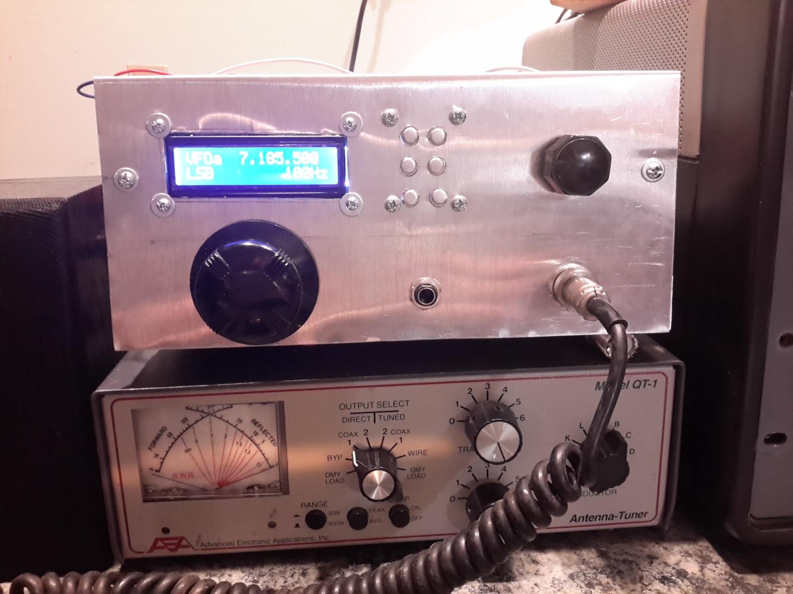
The picture shown above is how the rig looked at the time of my QSO with WD5HIO.  Later in the evening, I tidied-up the wiring a bit, but the circuitry remains the same.

One thing that I still need to do is implement a tone generator for CW:  When I started this project, I wasn't aware that the FCC had revised the regulations allowing this mode, so it wasn't on my radar.  That'll be handled in software, using the Arduino to generate the tone and cleaning it up with a RC LPF network.

Otherwise, there you have it.  I'm debating whether to mount it on a chassis and put it in an enclosure, or leave it as it is... The crudeness of the breadboard is growing on me!

Update: Added a few lines of code, LC LPF and an input line for the CW Keyer.  The Arduino did a marvelous job - told it the output a 1.5KHz square wave, and it did exactly that.  So, with the proper attenuators, I'm feeding the tone into the mic circuit to put the CW signal right in the center of the channel, and a little back into the RX amp to provide a side-tone.  Works great!

73 - Steve

Saturday, October 8, 2016

Back to the shack!

We've had some abnormally nice weather here in the Detroit area over the past few weeks, so I haven't been spending much time melting solder in the dungeon.

I did discover something new a few weeks ago: About 10 miles from me is an outlet of the computer chain Micro Center.  What I didn't know was that they started carrying Arduino stuff and other electronic parts and supplies - cool!  Better yet is that they've been running some sales: Uno boards for $5.00 and Pro Minis for $3.99.  So, I've stocked-up!

With my newly acquired boards, I've done some clean-up on the all-band rig and planker: The haywired breadboards have been replaced by (relatively) neatly-wired Nano and Pro Mini controllers on perf board, so the rigs look a little less scary.

I ran into something noteworthy when installing the Pro Mini in the Planker:  The "Raw" power supply input on the Arduino board is claimed to be good for up to 16 Volts, but nope... Good thing I bought extras, because the first one smoked at 12 Volts!  Not a big deal, I've had a bunch of LM78L08 regulators that I've been looking for something to do with.

About the only other thing I've accomplished is building the PA for the Planker.  Last year, I'd built Farhan's RF-386 amplifier, and abandoned it because I couldn't get it to behave.  The design looks solid, so I figured it had to be something in my layout - possibly the Manhattan construction?  I dunno.  Anyway, built another version and it's very well behaved and delivers a solid 5+ Watts on 60M with about -20dB/m input.  Cool!  Getting close to being QRV!

Right now, my bench looks like a disaster, so I'll post some updated pics after straightening things up a bit.  Hot dogs are tasty, but nobody wants to see the slaughterhouse.

73 de Steve N8NM

Tuesday, September 6, 2016

Steve's Eclectic Radio Blog

Welcome!

For years, I've enjoyed reading the blogs of other radio and electronic hobbiests and following the blogger's progress as he (she) converts an idea, first into a seemingly random pile of parts, and then into some sort of useful or superfluous (but nontheless fascinating) device.  

This got me to thinking:  I make some pretty cool and weird stuff, and I'm semi-literate, maybe someone might be interested in following along on some of my techno-adventures?  So, here we are!

To introduce myself:  I'm Steve Murphy, N8NM.  I've been a licensed amateur for over 30 years, extra class for 28 of those, but my fascination with making things out of junk started long before I was ever granted any sort of license, other than, perhaps, a library card.  As far back as I can remember, I was lugging home the carcasses of discarded TVs and radios, where I'd carefully dismantle them and sort and catalog all of the various bits.  God, I wish I were as organized today as I was at six or seven!

Since then, I'd built numerous small "homebrew" accessories, some of which worked as desired, and quite a few kits (most of which worked as designed), but it wasn't until about 20 years ago when I jumped in with both feet, designing and building my first homebrew receiver.  It was a relatively simple affair: 20 meter band only, using a FET VFO, MC1350P IF amplifiers, SBL-1 Mixer and product detector and LM-380 audio. It worked well enough to receive signals and I even used it for a few QSOs, but the VFO drifted horribly.   

Career and changes kept my homebrewing on the back burner for the next several years, when I again decided to jump in and build a "modern" version of the 6AG7/6L6 MOPA transmitter - covering 80-10m using Xtal or VFO control and with a regulations-compliant PI-L filter on the output.  This one worked much better, and I still occasionally use it today..

Then, a couple of years ago, I came across Ashhar Farhan's discussion of his new Minima transceiver.  I was already aware of his famous BITX rigs, but the Minima intrigued me because it was an "All band" transceiver.  So, I started analyzing Farhan's design, changing things here and there, mainly just because I could, and about six months later had my version of an 80-10m SSB/CW transceiver with general coverage receiver.  Though still unfinished, this is my current "main" rig.


This little rig uses two bilateral, termination sensitive amplifier blocks for the IF stages, homebrew diode-ring mixers for the mixer and product detector, and an LM380 driven by a 2N3904 for the audio.  Mic amp is a pair of J310s.  VFO and BFO are provided by the wonderful little Si5351, which is controlled by an arduino Nano, and the RF PA is currently a switching MOSFET, providing about 15 W on 80 down to about 2 W on 10.  Made hundreds of QSOs on this rig - having so much fun that I haven't been able to bring myself to tear it down for paint!

Another rig that I've been working on (and is setting on the back-burner at present) is my "Thermatron" receiver.  This is a general coverage SW receiver that uses tubes in the signal path, but is controlled by an Arduino Uno and uses another Si5351 for frequency/bfo.
It's really a cool little rig - it works, but needs a lot of refinement.  I plan on finishing this one up over the winter months.

So, what's in the works now? Well, a couple of things!  About a month ago, after some email exchanges with Pete Juliano, N6QW, I got the bug to build a 60m rig.  Since, in all of my prior efforts, I've started by having a chassis footprint and panel layout in mind, which never leaves quite enough room for all of the circuitry, I decided to build this one on a simple chunk of scrap board and figure out how to package it afterwards.  On seeing pics, Pete bestowed a rather brilliant name apon it: The Planker!  
So, here's the planker in it's current state - AF/IF/Mixer/BFO and low-level transmit stages are operational, next step is to complete the PA and band-pass filters.  Since 60m is channelized, I opted to use a single 7 segment LED (left over from an abandoned project) to indicate channels 1 - 5, with 6 being WWV at 5.000 MHz.  The receiver works great, and the low-level transmit signal sounds good and the IF bandwidth is within the FCC requirements, so I just have to give it some suitable "snot" to drive the antenna.  Looking forwared to that - 60m is the only HF band where I've never made a single QSO!

Meanwhile, I have several antique radio restorations in the works, including an Atwater Kent 20C, ERLA "Sky Rover" console, and a recently acquired NC-109 that - hopefully - won't require much more than a simple "recap".  Fortunately, I have enough bench space to support going back and forth between all of these active projects, which suits my short attention span perfectly.

So - this is me and what I do... From here forward, I'm going to share some of my fun with you, in much the same disorganized and unorthodox manner that I work in.  One day, I may document progress on some cool HB transceiver, then the next, write about replacing the mica wafer capacitors in the IF cans of a 50s GE or Zenith.  

Sounds like fun?  If so, please feel free to check back often!

73 - Steve N8NM