Saturday, February 17, 2018

Spontaneous Construction: The $20 Bill, or Oh No, Not Another 40m DC Receiver.

UPDATE: 22 February 2018 - Corrected Schematic
Thank you to Walter, KA4KXX, for kindly pointing out some errors in the "toroid table" at the top of the "Preliminary 2" schematic previously published here.  This has been corrected in the "Preliminary 3" schematic below.


This project started last weekend, on a whim after my Grandson, Austin, came over and asked if we could "Make some circuits".  So, I started putting together a low powered audio amplifier and it blossomed into a pretty competent little direct conversion receiver.

If you follow Bill, N2CQR's SolderSmoke blog, you know that he's working on a simple DC receiver of his own, which, along with his aversion to using the magic chips, served as inspiration for this rig, which is how it got it's name: $20 is my guess at what it'd cost to duplicate, and Bill, of course, is Bill.  The alternate name is based on my belief that the last thing the world needs is another 40m DC receiver.


As with most of my other projects, the chassis is bent from a combination of 20ga and 22ga galvanized steel.  I had just enough in my scrap pile to build the chassis and cabinet, which is currently out in the garage while the paint dries.  The decals were left over from the set I purchased from Radio Daze for the Echophone EC-1B.  Waste not, want not.

This is one of my few projects where I didn't steal any circuits from anyone else; I designed it in my head, refined it using LT Spice, and built it Manhattan style, and the thing worked perfectly right out of the gate - the only tweaking that I had to do was some futzing with the inductor in the VFO to get it to cover the entire band.

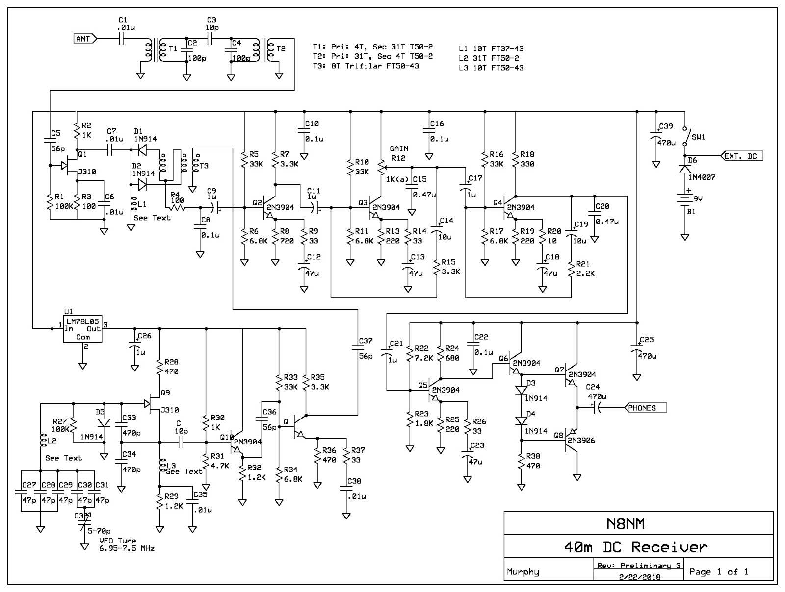
The circuitry is pretty simple: Signals first pass through a band-pass filter and then hit an FET preamp before arriving at the input of the diode product detector, where they're converted to baseband audio and applied to the audio amplifier string. At first glance, it might appear that I've got way too much gain, but if you look again, you'll see that the middle two stages are feedback amps and don't provide that much gain, but they're very stable and dead quiet.

Also, the audio passband is tailored to start rolling off frequencies above about 2KHz.  I thought about making it tighter, but wanted to be able to use it to listen to SSB; For some reason, I get a kick out of listening to the guys running their state-of-the-art megabuck rigs on a junkbox rig.  

The output stage is a push-pull 2N3904/2N3906 pair that provides a couple dozen milliwatts of power, plenty for headphones and adequate for a speaker if you're using it in a quiet room.

The VFO is a basic series-tuned Colpitts, lightly coupled to a buffer amp and then to a gain amp.  The capacitors are all NPO, and the inductor is wound on a T50-2 core and "hot glued" to the board.  There's a slight drift at start-up, but after 15-20 minutes, it settles down and is more stable than it has a right to be - watching signals in the waterfall of WSJT-X, I see no drift at all over several minutes.  The only magic chip used in the rig is an LM78L05 to regulate the VFO voltage, only because I don't have any suitable Zeners in my junk box.

What really impresses me, though, is how incredibly quiet the receiver is: Put on phones and crank the audio without an antenna and you'd swear that you forgot to turn it on; there's NO background hiss at all - something that's bothered me about my prior DC receiver efforts.  Connect the antenna and you'll quickly reach for the gain pot - signals seemingly jump out of nowhere!

The rig can be powered either from its internal 9V battery or a 12V bench supply.  It is a bit current hungry, drawing about 70mA, which is why I added the provision for external DC power.

As I mentioned, I started this last weekend and worked on it a couple of hours each evening and another 3-4 today, so yes, one can build a practical rig without giving up all semblance of a life outside of the shack.

There's a major CW contest this weekend, and the wall to wall signals make using a DC receiver challenging, it didn't take long to get the hang of using it and was able to make several DX contacts.

I don't often wear a hat, but if I did, I'd tip the brim toward Bill in Falls Church for giving me the idea to build a (mostly) discreet component, hardware defined radio.  I have a feeling that more will follow, but I really need to get back to the SDR-2018 that's sitting here taunting me.

Friday, February 9, 2018

Echophone EC-1B: Finally finished!

Finished - for the second time.
Let's start this post with a tale of woe:

I actually had this thing ready to go early this week, but, since it'll be a gift for my grandson and subject to abuse, I wanted to shoot a couple of coats of clear over it to give it some protection.  My idea an intention were both good, but my execution sucked wind!  Which leads to the last statement in my last post:

Don't use lacquer over enamel.

I've known this for some time, but have been successful in cheating fate through multiple test-sprays over well cured enamel base, and abandoning the thought if there was any sign of an adverse reaction.  I did that with this radio and, by all indications, it looked like it'd be OK.  It wasn't...

Within a few minutes, my previously perfect hammer-tone finish had severely wrinkled in spots.  Dammit!  Oh well, nothing else to do but strip it down and do it over - this time clearing with a compatible product.

Paint-wise, the second effort turned out better than the first, but my decal application wasn't as good.  But, it's adequate, so I'm not going to mess with it.

I can't help but be impressed by the performance that they were able to wring out of such a simple circuit.  Assuming it's intended purpose was casual shortwave broadcast listening, it's remarkably adequate.  For amateur use, though, it's challenging. 

In developing the specifications for the original Zenith Trans-Oceanic, Commander MacDonald insisted that one shouldn't need "micrometer fingers" to tune the thing.  With this set (and the S-38s), such digits definitely come in handy, especially when tuning SSB signals.

But, once you calibrate your fingers, it's completely possible to tune SSB stations.  It's not easy, but it can be done.  I did incorporate one simple modification while re-working this set to aid in CW/SSB reception:  When in "CW" mode, the original design defeats the AGC by putting the cathode of the IF tube right to ground.  This sets the gain to maximum, which causes strong signals to "override" the BFO.  Replacing the short-to-ground with a 470 ohm resistor reduces the gain just enough to where 90% of the signals can be resolved without "overriding" the BFO.  Cool!

Weak points?  Well, these were designed to be cranked-out as cheaply as possible, so they suffer from mechanical instability.  The dial resolution is vague, and, the IF filtering is quite broad.  Again, perfectly fine for casual AM SWBC listening, not so much for CW/SSB.

Other than my epic paint failure, this has been a fun project and I'm actually having a lot of fun dialing around the bands with the little fellow.  So much that, since I'll be giving this one away, I'm going to look for another one for myself!

Tuesday, February 6, 2018

Back to the SDR-2018: Examine Low-Pass Filters

To give credit where it's due, I completely stole this filter topology from Icom and adapted it to my circuit and junkbox inventory - it's NOT my original idea, I just think it's cool.

Here's the 40m LPF from my SDR-2018, as modeled in LT-Spice:

 When I first saw this circuit, it had me scratching my head for a moment.  In essence, it looks similar to pretty much every other LPF, but wait, what's with C4 and C5?  Then it hit me: They work in conjunction with the coils to create traps at the 2nd and 3rd harmonics of the 40m band: L2/C4 are resonant at 21 MHz and L1/C5 at 14 MHz.  Nice!

Here's a sweep of the circuit without C4-C5:
  And here 'tis with them:
Here's what makes it cool: Nobody likes winding toroids, but with the standard Chebychev or Butterworth topologies, you'd likely need at least one, maybe even two more stages to ensure the 2nd harmonic is down >40dB.  That's one or two more toroids to wind, not to mention the extra caps and board space.  Here, we get massive harmonic attenuation with only two additional caps. I don't know about you, but I find that appealing.

It's easy to apply to an existing design as well.

Pete, N6QW, recently posted on his blog (n6qw.blogspot.com) about the driver/power-amp circuit he's developed for his IC transceiver, that includes a low-pass filter that, in his comments, he mentions may not be adequate.  So, let's look at it:


Would it work?  Probably, but with a single-ended output, I'd be a little concerned about the 2nd harmonic. 

Now, we calculate the values of capacitors that will resonate with the coils on 20 and 15 m, select the nearest standard values and plug 'em in:


And Fannie's your aunt.  Look at that rejection, just look at it!


Note that I did have to tweak L2 to achieve resonance with the 47pf cap, one could probably accomplish this by simply spreading out the windings a bit, or, worst case, removing one - no big deal.

My next post will be the final installment of the Echophone restoration, and includes a tale of woe. Never lacquer over enamel.  Just don't do it.

Friday, February 2, 2018

EC-1B Part IV: Bodywork and Repaint


Now that the electronics have been whipped into shape, it's time to address the sad fact that the little receiver still looks like crap; with large sections of paint loss and corrosion, it's a bit past the point where a simple "touch-up" is possible.  Nope, gonna have to strip the little fellow down to his birthday suit before dressing him back up.

I was a little surprised how tough the remaining finish was; my original thought was to chemically strip it, but it took forever for the stripper to soften the finish, so I resorted to brute force: The dual-action (DA) sander.  Twenty minutes later, I was looking at bare metal!

As it turned out, I would have had to break out the DA anyway as the rust had pitted the metal quite extensively, so giving up early on using chemical strippers actually saved me some extra effort, not to mention the mess.  

While I had the thing in bare metal, I hammered out a few minor dings and dents and straightened the speaker louvers, which always get bent on these radios.  When I was happy with it, I prepped the metal for primer and then paint.

Here I took a little artistic liberty and deviated from the original wrinkle finish, mainly because I've had mixed results with it in the past.  Instead, I went with a hammertone grey made by Rust-Oleum.  I'm reasonably happy with it, though it's not my best effort... I think it'd have turned out better if I had let the garage warm-up for a day beforehand; it was about 10 degrees F outside and maybe 50 degrees F in the garage when I sprayed and it didn't "lay down" for me as well as it has on other projects.  I guess it's OK, but I may strip it back down and start over.  We'll see.

In the meantime, the label decals have arrived from Radio Daze, so I'm going to let this cure for a few days (if I don't decide to strip it) before applying them and a coat of clear enamel to protect them.  Then, once that has a few days to cure, I'll start reassembly.  I scored a set of original knobs from Ebay, they should be here by then.