Tuesday, December 19, 2017

Non Sequitur: Parts Scrounging and 6L6 Transmitter

MOPA rig with N3ZI VFO
A recent post on the SolderSmoke Blog got me thinking about the time-honored amateur tradition of building things out of parts obtained curbside.

I think I was probably eight or nine years old when I began lugging home and systematically dismantling junked radio and TV sets, something that became almost an obsession with me in my pre-teen years.

People threw away some cool stuff in the early 1970s, when one could count on harvesting at least one old black and white television set from among the household rubbish set out for collection, and I got good at retrieving them.

Garbage night was something of a weekly holiday; I'd rush home from school, grab my bike and begin hovering the neighborhood, hoping to catch someone in the process of dragging one of the old behemoths to the curb.  If my reconnaissance mission were successful, the next challenge faced was getting the thing home.  With smaller sets, I found that I could dismount my steed and precariously balance my bounty on the seat and handlebars of my Sting-Ray bicycle.  Larger, console sets posed a greater challenge, because I'd have to zip home, grab a wheelbarrow and zip back before someone else claimed my prize.  Much to my parent's dismay, my success rate was pretty decent.

With the derelict safely on the workbench, I'd begin the laborious disassembly process.  Every part would be identified, carefully unsoldered (no lead clipping for this kid!) and added to my ever expanding inventory.   Tubes were carefully sorted and stored in egg cartons, resistors, capacitors and small inductors were taped to index cards and categorically filed for easy retrieval, while the crown jewels: transformers, would be stashed under my bed in old shoe boxes.

Meanwhile, I'd be pouring over the various books and magazines, dreaming of building some of the featured projects.  Unfortunately, I wasn't quite there yet.

I wonder whatever happened to all that junk?  I should ask my mother.

Fast forward another 35 years.  While I don't practiced "Alley Picking" like I did as a kid, I had somehow amassed another hoard of salvaged parts.  But, this time, thanks to skills acquired over time and the endless resources available on the web, I knew I'd be able to do something with them.

In the search for candidate projects, I came across an article from the September 1964 Electronics Illustrated on KH6SKY's web page that described a simple 6V6 CW transmitter built from junkbox parts, appropriately named "The Scrounger".

The Scrounger was built on an inverted cake pan, which, enjoying cake as I do, appealed to me.  So, I built my first Scrounger prototype, which was reasonably faithful to that described in the EI article.  The damned thing actually worked, and I made quite a few contacts until disaster struck:  I accidentally set some papers down on my J-38 without a crystal in the rig and zorched the transformer.

That unfortunate incident taught me of the importance of protective bias, and armed with this knowledge, I set about building the improved version of the transmitter pictured at the top of this entry.

Unlike the original Scrounger, this version employs a 6AG7 and 6L6 in a Master-Oscillator-Power-Amplifier (MOPA) circuit, complete with bandswitching and a PI output network.  Of course, I added protective bias and changed from cathode to grid keying. 

Having addressed those "shortcomings" of the original Scrounger, I became dissatisfied with being limited to crystal control, so I added a synthesized VFO based around one of N3ZI's AD9850 boards.  Since the AD9850 doesn't have enough "oomph" to drive the transmitter, I added another 6AG7, making the rig a three tube affair.

It's actually a pretty decent little rig now, but has a much different character than my first version, mainly because it uses mostly new and Eastern Bloc surplus parts rather than those scrounged from the junk.  It's still got soul, but it's of a different nature.

I've still got the remnants of my original Scrounger, I should rebuild it someday.

Friday, December 15, 2017

Back to the SDR rRig: Band and Low-Pass Filter Boards

I doubt anyone really likes winding toroids, and I'm no exception.  But, unless you're in a position to hire someone to do it for you, you gotta suck it up and get it done, which is what I've been doing for the last three nights.

Below is a pic of the nearly completed bandpass filter and low-pass filter boards for the SDR-2017.   Nothing high-tech about 'em, just capacitors, coils and relays.


I think I mentioned in a prior entry that I'd basically stolen the basic design of the filters from those used in the IC-735, though I did massage them a bit using LT-Spice.

If you look carefully at the boards, you'll see that I'm using Manhattan style construction using small round pads.  I kind of stumbled onto the idea of making these pads after ordering some el-cheapo PCB stock that doesn't like being cut with shears, which is how I've always made Manhattan pads in the past. 

Amongst my seldom used tools is the hole-punch set pictured below.  I found that, by inserting the PCB stock into the punch upside-down, I was able to consistently knock-out perfect circles in various sizes.  I've used Rex Harper's ME Pads and like them, so to pay tribute to Rex, I call these "My Pads".

Hole punch used to create Manhattan Pads. 1/8" pad shown near the face of the ball-peen hammer.

Inverted cheapo PCB stock in punch. I found it necessary to punch the stock from the backside, otherwise the phenolic tended to shatter.

Thursday, December 14, 2017

Y723-2017 Schematic

Here it is:

Pretty straightforward.  The "front end" variable caps and inductors were salvaged from the Zenith chassis.  4.7pF caps were added across L3 & L5 to get the dial to track properly on FM.

The variable inductor in series with the 10.7 MHz resonator was added to get the resonator onto the same frequency as the ceramic filter.

The two SPST switches are sections of the Zenith's rotary AM/FM switch.  One section is open on AM and closes to the 5 Volt line on FM. This is applied to the TA2003 IC to switch it over from AM to FM and back.

The other switches in about .05 uF of capacitance on the audio output of the TA2003 (FM De-Emphasis.)

One LM324 section is used as a Baxandall tone circuit that can cut or boost the high and low frequencies by about 8 dB.

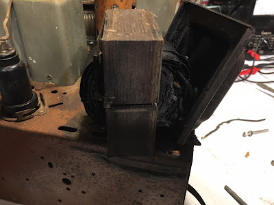
The transformer was salvaged from an old Motorola battery charger.


Sunday, December 10, 2017

Spontaneous Construction: Y723-2017

When you work on "antique" radios, you can't exactly ring-up the manufacturer and order replacement parts, so you tend to hoard things that most people would consider rubbish.  It may seem like odd behavior for otherwise reasonable people, but it is completely rational; you never know when you or a friend might need the epicyclic reduction drive off of the tuning condenser for a 1938 Philco.  It's always nice to have a few on-hand.

But, left unchecked, the hoard will eventually grow to an unmanageable size.  If you forget that you've got that 1938 Philco carcass in the junk pile, what good is having it at all?  None. Like it or not, you have to occasionally thin the herd. Unfortunately, that requires making some hard, cold-blooded choices.

Such was the case with this Zenith Y-723 with the cracked case and partially disassembled chassis.  It had already given up a number of parts so that other sets could live on, but I was still having a hard time with the idea of pitching it.

Then the thought occurred to me: The tuning mechanism and it's associated LC components are still there, Why not build a "modern" radio around them?

Normal people don't think of things like that, and only a real whack job would actually do it.

And with that thought, I present to you: The Zenith Y723-2017!


The salvaged tuning section from the defunct Y723 found itself sharing a chassis (fabricated from scrap ductwork) with a power supply built around the transformer from an old Motorola desk charger.  Below the chassis is the RF/AF circuitry; the radio is based on the TA2003 IC, and the audio amplifier uses a Sanyo LA4425A.

The speaker is a 3 1/2" model of unknown origin, another junkbox treasure.  I'm a big fan of these mid-50's Zeniths, but have to admit that their tone sounds a lot like the plastic case.  So, to get away from that, I built an MDF enclosure for the speaker, hoping that it absorbs some of that cabinet resonance. The new chassis and speaker box fit snuggly into the original cabinet, which remains cracked, albeit reinforced internally with lots of hot-glue.

How's it work?  Great!  AM reception is on par with the original set, but FM is significantly better: It's far more sensitive and just plain sounds better.  The LA4425A delivers enough audio to drive the orphan speaker loud enough to fill a room, and the audio doesn't sound like it's originating from a plastic cave.

That said, the low-frequency response of the orphan speaker was a bit limited, so I retroactively cobbled-in a Baxandall tone circuit built around one section of a LM324 quad op-amp.  This is adjusted internally; I didn't bring the controls out because I envision it as serving only to equalize the audio response, not as something I'd be playing with.

I'm still not sure what I'll do with this, but I won't be throwing it out anytime soon.

Wednesday, November 22, 2017

Wow!

Holy cow!  It's already close to a month since I've posted anything!  Where does the time go?

Truth is, I've gotten side-tracked by a couple other projects while waiting on some parts for the SDR-2017 project.

The first is an old Zenith 9-S-262 "Shutter Dial" that I electronically serviced for a friend.  Wow, what a great old radio!  The thing sounds fantastic and, in spite of needing multiple repairs, has been super easy to work on.

When I picked-up the set, I had a bad feeling about the power transformer, which ended up being justified because it was toast.  Not just toast, but toast burnt crispy black.  Bummer.

 Fortunately, my habit of hanging on to crusty old radio carcasses came in handy and I had a suitable replacement. Cool! 

After swapping the transformer, the rest of the repairs were routine:  Replacing first the electrolytic filter caps and then the old wax-paper coupling and bypass capacitors. 

Once this was done and new drive belts installed, I was able to give the set a "shake-down" test to evaluate any other problems that might be lurking.  I was happily surprised to find that, other than dirty/noisy controls, the only other problems were a dead "eye" tube and sluggish "Robot Dial" motor.  

Rebuilding the motor was trivial: Take it apart, clean out 80 years worth of crud, lubricate the bearing surfaces and reassemble.  About half an hour's work had it working like new. 

They eye tube required a little creativity.  Zenith originally used a 6T5, a tube that is very scarce, with good examples selling for hundreds of dollars.  That tube was long-gone from this set, having been replaced with the fairly common 6U5.  Electrically, the tubes are interchangeable, but the eye pattern is different.  I swapped the 6U5 for one that I had in my junk collection, but, alas, this tube was also very weak.  So, off to Ebay.

6E5 tubes are reasonably plentiful and affordable, and are pin compatible with the 6U5, but have different gain characteristics; they're a bit "hotter", which means that the eye will be partially closed during no-signal conditions, and will close beyond 100% on strong signals.  But, that's an easy fix: knock down the AVC voltage to the grid with a simple resistor divider and it'll work just fine.  In this case, I used 100K in series with the AVC line and 1MEG to ground.  Perfecto. Finis.

With that project out of the way but still waiting on parts to get back to work on the SDR-2017, I jumped into another "spontaneous construction" project:  This one being an AM/FM broadcast receiver using a $0.23 TA2003 IC.  Unlike many IC based radios, this one actually works well - more to come.


Thursday, October 26, 2017

SDR-2017: Progress and Modularity

If you've read my earlier posts, you know that I'm a big advocate of the modular approach to design and construction, and that it all starts with "Noodling" - thinking about what I want the rig to do and laying-out how I want to accomplish it in a block diagram, which will serve as the project's "road map". 

I used to scratch out these diagrams on paper until I discovered the Yed program, which is now my tool of choice.  It takes a little more time, mainly to get all the boxes uniform in size and all the lines straight, but I find that process also helps me think in a little more depth than I do when drawing on paper, and it's certainly easier on trees.

Anyway, above is the SDR-2017 diagram that I "finalized" back in August, and I've "X" marked the modules as I've completed them. Notice that I haven't deviated from the original design concept; the diagram keeps me on track and prevents succumbing to "feature creep"!

 At this point, I've got a pretty respectable software defined receiver that covers from below the AM broadcast band up to the lower VHF spectrum, where it begins to run out of steam around 100 MHz.  Good bones for what'll ultimately become a 160 to six meter transceiver.

 My primary use for this rig will be on the amateur bands, but I also want the ability to occasionally use it to receive shortwave broadcasts, which makes designing the bandpass filter networks a bit more complicated than it would be otherwise.  Being lazy, I borrowed much of the bandpass filter design from a commercial rig (IC-735), with some tweaks to optimize the circuit based on this application and what I have in my junkbox. 

What I did first is create models of the Icom circuit in LT Spice, so that I could see what the Icom designers came up with.  Below is a model of the filter for the 160 Meter band:
 In this case, where I'm shamelessly stealing someone else's proven design, these models wont be used so much to tweak the design as they will to confirm that, once constructed, it's working as it should - more on this in a minute.

My next step was to build the inductors.  Sure, I could just order them from Mouser, but what's the fun in that?  So, I spent a few hours working with a spreadsheet that I put together years ago for this purpose, which spit out the number of turns and type of core for each filter element, then spent a few more hours winding the bloody things.  I don't know of anyone who enjoys that, but if you do, something's wrong with you...

With all that info, I drew the schematic shown below and began putting the filter board together.
 Rather than using diode switching as in the Icom, I'm using relays for a couple of reasons: First, I haven't had much luck homebrewing diode RF switches; I can get 'em to work, but the isolation is always poor.  Second: I got a good deal on the relays.  I started construction with the input switches, and will add the output switches as each band's filter is completed.  Doing it that way makes building the filters easier because I'm not reaching over the relays while working.

Speaking of that, there's been significant noodling involved in determining the physical layout of the filter board.  The board itself is 6" square, and I've divided it into seven "lanes" - one for each band - of about 0.75" each.  The input switches are at one side of the board and the outputs on the other.  Since the RF signals on this board are going to be low (<0dBm), I don't expect that there'll be any crosstalk between the filters, but if so, I'm leaving room to install shielding dividers between each lane.  I'll post pictures as I get further along in the construction.

As of last night, I've completed the 160m filter and "swept" it using my spectrum analyzer (Rohde & Schwarz FS-315.)  The response matches the LT Spice model so closely that it's almost spooky!  The curve is virtually identical, the only differences are in the loss (actual filter slightly better than model) and frequency of the peak (actual filter peaks slightly lower in frequency, but still FB in the amateur band.)  Excellent!

Once I have this board completed, I'll circle back and complete the T/R switching and mic audio circuits; much of this is incorporated into the Softrock hardware and Quisk software already, so that *should* be fairly simple... We shall see.

This is the point in any project where it becomes exciting and I have to fight the temptation to "pull an all-nighter" to get things done.  I'm getting close to retirement when that'll become practical, and man, am I ever looking forward to that!


Tuesday, October 17, 2017

SDR-2017: Assembly, First Light and Audio Tweaking

Receiving AM Broadcast station - note the IBOC "sidebands".
After lots of "noodling", I'm finally getting to the fun part: Putting it all together. 

Touching a bit on the mechanical aspects: I didn't want to fall in to my usual trap of trying to squeeze 10 pounds of stuff into a 5 pound bag, so this rig has a large form factor when compared to my others.  Dimensionally, it's 16" wide, 12" deep and 6" high, so with any luck, I won't be building each module 3 times in effort to make it fit into the smallest available space.  We'll see how that goes.

Because of my limited metal working skills and facilities, I've built the chassis from 26 gauge galvanized steel.  Getting this rather flimsy material formed into a rigid housing took a little thought and some trial and error, but it's working out reasonably well.  Basically, it's a lot like modern cars in that it's a box that gets its strength from being made from smaller boxes.  So, while it's very light in weight, it's structurally rigid, and very easy to work with - except for the bleeding part; some of the edges are pretty sharp.

Electronically, I haven't deviated from the topology that I laid-out in my initial block diagram:  The touchscreen equipped Raspberry Pi, running Quisk in "kiosk mode" talks to the Arduino that handles all the hardware switching and programming of the synthesizer, while a modified "Softrock" connected to a USB soundcard handles the modulation/demodulation.  Ahead of the Softrock is a diode double-balanced mixer that converts the received signals up or down to 9 MHz.  This is all working fairly well, though there's still a lot of refinement work to be done.

An example of this is in getting the receive audio sounding decent.  My original intention was to take the line audio out of the pi and feed it, through a 10K pot, to the LA4425A power amplifier.  This works, but picks up a ton of stray computer noise unless I significantly load the input to the power amp, which reduces gain more than I'd like.

The LA4425A has a rather high input impedance, somewhere in the 10s of K Ohms, while the output of the on-board soundcard is fairly low Z, and I think this mismatch is causing the problem.  So, I'm going to try a simple common-base transistor amplifier between the soundcard and volume control. 

The common base amplifier's characteristics are: Low input impedance, less than unity current gain, moderate output impedance and relatively high voltage gain; exactly what I think is needed.

I've built enough transistor amplifiers that it's almost become second nature, but I still like to go through "the design process" first, then model the circuit in LTSpice before melting any solder or frapping any silicon.

When it comes to designing a common-base amplifier, I tend to approach it in much the same way as I would a common emitter circuit.  R1 and R2 form a voltage divider that's "stiff" enough, current-wise, to keep the base voltage at about 2.1 volts.  This biases the circuit so that the drop across R4 will be about 1.5 volts.  Dividing 1.5V by 100 Ohms gives us the quiescent current flowing through the device, about 15 mA. Next, I want the collector to be able to "swing" about a volt, so I chose a resistor of 560 Ohms, which has the collector resting at about 3.25 volts.  Cool.  

Plugging these values into LTSpice, I was able to see that the model confirmed the numbers that I'd come up with.  Yes, they're not exactly the same, due largely to my assumption that the B-E Voltage drop was 0.6V, but still well within in the ballpark.  
 
Initially, I ran the model without C3 in place, and the predicted gain was just under 18 dB from a few hundred Hz to well beyond the audio spectrum.  Since this isn't a hi-fi, I added C3 so that the gain rolls-off above about 3-4 KHz.  Since I had the circuit already "running" in LTSpice, I simply plugged-in different capacitance values until I got the response curve I was looking for, but this could be determined algebraically with just a little more effort.  
 
This response shaping cost  around 4 dB in overall gain, which is insignificant in this case because I'll still have more than enough signal to push the LA4425A to it's maximum.  Actually, I think I'm probably going to have to reduce the gain a bit... Maybe not, we'll see.


The next step will be building the circuit, plugging it into the rig and seeing if it works as intended.  Stand by!

73 de N8NM


Wednesday, October 11, 2017

SDR-2017: More Controlling the Beast

The diagram (and board) are starting to fill-out nicely! I've added a couple of things since my last post:  Outputs for the cooling fan for the Pi and for switching the low-pass and band-pass filters.

The fan output is straightforward:  I use a 47 Ohm wire-wound resistor to drop the voltage and slow the speed a bit, and a 470 uF capacitor to eliminate any electrical noise. Easy peasy.

The filter select lines were slightly more involved.  Since the Arduino will always be aware of the frequency of operation, I added some conditional statements within the sketch to activate the appropriate filter-select lines based on that frequency. To conserve the Arduino's I/O, I'm using a 74AHCT138 3 to 8 bit decoder.  I'll throw-up (unfortunate choice of words) the code sometime in the next day or two.

While this version of board and code are doing their intended duties, they're still very much in the preliminary "proof of concept" stage; I may want the Arduino to perform some other tasks, such as a CW Keyer, that rely on pin-change interrupts, so I need to look at my port choices to work around the interrupt limitations of the Arduino.  Right now, the only interrupt-driven thing we're doing is reading the encoder, so it's not an issue...

73!


Monday, October 9, 2017

SDR-2017: Controlling the Beast.


My primary goal of this project was to envelope modern SDR software and hardware in a traditional package, making the user experience less "black boxy" and more familiar to those of us who've spent our lives operating what's now considered "Legacy" hardware.  In other words, I want the operator to sit in front of a RADIO rather than a computer monitor, keyboard and mouse. 

What I'm finding to be a challenge is in how to integrate "off-the-shelf" systems and hardware into the form of a traditional radio.  Getting it working is only half the battle, the other half is getting it to work the way I want it to.

An example of that is the simple matter of turning the rig on and off. 

Backing up a bit:  Architecturally, the "back-end" of the rig is a modified SoftRock RXTX V6.2 connected to a Raspberry Pi and 7" touchscreen via a USB sound card.  This makes for a fully-functional "black-box" transceiver on it's own, but it's hardly a traditional package; I want knobs, switches, and the ability to cover all HF bands (possibly including 6 meters...)  That's going to take some more hardware - and a LOT of noodling!

Since I've already built several rigs using Arduino controlled Si5351 synthesizers, that was a natural place to start - I've already got working code to handle this, plus switch the necessary filters and all that jazz.  The trick was in getting the Arduino to talk to the Pi so that the frequency displayed by Quisk would track that tuned by the Arduino.

Getting that working wasn't as bad as I'd thought, thanks to Pavel, CO2WT's FT857D library.  By integrating this with my Arduino code, I was able to take advantage of the off-the-shelf Hamlib libraries to get the Arduino talking to the Pi: Quisk think's it's controlling an FT-857.

So, at that point, I had two single-board computers talking to each other and the encoder/synthesizer and all was good.  All was good, except that I had no clean way to turn them all on and off together... That took a few nights to figure out!

Referring to the diagram above, switch S1 is a momentary pushbutton that, initially, is shunted by 1/2 of K1.  When S1 is pressed, power is applied to the Arduino and Pi through a DC/DC Converter (more on this later.)  Once the Arduino is initialized, port D5 goes high, turning on Q1, energizing K1. Meanwhile, the Pi is still booting; once it does, it, too, sends a high (from GPIO23) to the base of Q1.  In that manner, Q1/K1 will be turned on when the Arduino OR the Pi are running. 

Why the wire OR?  This drove me nuts:  When a serial connection is being established to an Arduino, the first thing it does - by design - is force a reset.  So, what would happen is that the Arduino would boot first and suck-in the relay, but when the Pi'd boot a few seconds later, the whole thing would shut down.  The "Wire OR" keeps the relay energized while communications between the devices are being established. 

Once powered-up, the "cold side" of S1 is re-routed through the 2nd set of K1's contacts to Q2 and Q3.  So, pressing the switch will then turn those transistors ON, placing logic LOWs on Arduino port D4 and the Pi's GPIO24.  Code in the Arduino switches port D5 Low, and a daemon running on the Pi initializes it's shutdown sequence such that it's final act is bringing GPIO23 LOW, de-energizing Q1 and K1, killing power to the DC/DC converter module.

It took a hell of a lot of head scratching to get this working, but man, is it ever cool!

Going back to the DC/DC converter for a minute:  My first pass at providing regulated 5V used a LM-317 driving a TIP3055.  It worked, but ran hot, and I really didn't want to have to bury a large heat sink in what'll eventually be the bowels of the rig.  So, I sat down and started designing a switching regulator, and looked over at the tray on my desk that holds paper-clips and other such office effluvia - everyone's got one of those... Anyway, in that tray was one of those USB converters that plug into a car's cigarette lighter; I'd gotten it as a hand-out at a trade show and never used it.  Checking the specs, it was rated for 3.4 Amps at 5V - perfect!  I cracked it open and installed the guts in a small shielded box that I bent out of galvanized flashing, and, as they say: Bob's your uncle.

With this milestone out of the way, I'm looking forward to the next, and relatively simple task of designing/constructing the audio amplifier stage. 

73!


Saturday, September 30, 2017

New Rig: SDR-2017

It's been almost a month since my last post.  It's not that I haven't been busy, but because I've been doing some high-intensity noodling and trying, with limited success, to get a handle on coding in Python.  But, I'm making progress and finally at the point where I can cut/bend some metal and melt some solder!

In previous posts, I mentioned that I'd be doing a "Software Defined" rig as my next project, but I didn't want to simply regurgitate what others have done. No, I want my stink all over this one.

I started experimenting with SDRs in the mid 2000s when I stumbled across Tony Parks, KB9YIG's early Softrock kits.  These are really incredible little radios, and lots of fun to build - so much so that I built way several, including a couple that I never really intended to use, one of which I modified and re-used in this project.

As nice as Tony's kits are, once the novelty wore off, I lost interest in the operating experience, which is, to me, more like operating a computer than a radio.  This is by no means a criticism, just that it wasn't for me - I prefer a radio that "feels" like a radio.  So, I shelved the SDRs and went back to using more traditional radios at the same time that SDRs started becoming insanely popular with the rest of the amateur fraternity. 

Anyway, I started getting ideas for this project earlier this year when I came across a 40m Softrock receiver that I'd forgotten about, hooked it up and marveled at how competent a receiver it is.  Then, while rummaging through my desk at work, found one of my "surplus" Softrock transceivers hiding in one of the drawers.  That got the wheels turning: Why not build a "real" radio around it?  So, here we are...

The Softrock serves as the modulator/demodulator stages in the new rig, and is controlled by an embedded Raspberry PI 3B running N2ADR's Quisk software. The Softrock has been adapted so that it's frequency is controlled by one clock of the venerable Si5351 in much the same way that others and I have used it to provide the BFO signal in conventional rigs.  In other words, the Softrock is tuned to the IF signal.

The Si5351 is controlled by an Arduino Pro-Mini, that's also used to select the appropriate band and low-pass filters and handle all of the rig's switching duties.  The Arduino and Pi talk to each other via their USB ports: The Pi tells the Arduino when the frequency or band is changed in Quisk, and the Arduino tunes the Si5351 and switches the filters.  Conversely, when the frequency is changed using the rotary encoder, the Arduino tells the Pi about it and Quisk updates the operating frequency.  Cool!  A big "Muchas Gracias" to Pavel, CO2WT, for his fantastic library that makes the Arduino look like an FT-857D, allowing me to use the standard Hamlib libraries to make this all tick.

Referring to the above photo, the pot at the lower left is the AF gain.  I'm using an LA4425A amplifier to bump the soundcard's line-level output up to a few watts of glorious, room-filling audio.  In the upper left corner is a momentary switch used to power the rig on and shut it down gracefully; I've got the first part working, but need to debug the shut-down code (Damned Python.)

The display is a 7" touch-screen, which is about the perfect size to control Quisk in small-screen mode.  The Pi is attached to the rear of the display using a homebrew bracket/enclosure.  I found that the Pi would overheat after running for several hours, so I combated that by installing a small cooling fan on the Pi's enclosure.  I can now leave it running for days without it going into melt-down.

Left of the display is a 100 PPR encoder that I got ($20) from Marlin P. Jones. I love the resolution of the encoder, but am not wild about the clicky detents and intend to see if I can defeat that feature.

So, at this point, I have a working SDR operating at 9 MHz - which deserves mention:  9 MHz is a good single-conversion IF on all HF bands except 17m, where it's a pain to filter the 2nd harmonic of the BFO from the transmitter's output.  But, since there are no fixed IF filters being used and the 2nd LO is programmable, I can change to a 17m friendly frequency with a few lines of code.  Excellent!

That's where I'll leave it for now.  Until next time,

73 de Steve N8NM


Sunday, September 3, 2017

Huffing Lacquer

After building up the preamp for my Crosley 86CR, I decided that it was time to finish that radio completely.  You see, I repaired, stripped, grain filled and prepped the thing for lacquer over two years ago, and have using it in a partially assembled state ever since.

I like working with lacquer because it gives me lots of somewhat valid excuses for procrastination:  It's too hot, too cold, too humid, etc.  Since we've had temps in the upper 60s to low 70s, with low humidity, for about a week, I just couldn't put off breaking out the HVLP sprayer and going to town.

Unfortunately, I didn't photo-document the process... I never intended to write it up... but here we are.  I'll do my best to paint a word picture.

Here's what I started with in 2015:

It was actually in decent shape, though there was some veneer damage to the dial panel and a few dents from having things dropped on or banged into it.

To repair the veneer, I removed the dial panel and removed a section of veneer from a location that is hidden behind the side panel and surgically grafted it into the spot where the exposed veneer was damaged.  It took a few hours, but turned out well - the repair is all but invisible.

To work out the dents, I employed the XYL's iron and steamed them out.  This was easy - just lay a moist cloth over the dent, heat it with the iron and the fibers of the wood expand and the dent disappears.

After these and a few other minor repairs, I completely stripped the cabinet using Citru-Strip.  I like this stuff because it doesn't stink, so I'm able to do it indoors.  The trick to using it is to get a feel for how long to leave it on before scraping it off; too soon or late and you make extra work for yourself, but find the sweet spot and you'll have naked wood in no time.

Once stripped, it's time to sand.  This set has some fairly beefy veneer, so I was able to get quite aggressive with it in some spots.  It's not rocket science, start with a coarse grit and keep working it and progressing to finer grits until it's smooth.

But, even when it's smooth, you still have to fill the pores, which is my least favorite part of the job.  Ever see a refurbished antique that, when viewed from different angles, looks like it's had glitter splashed on it?  They skipped this step.  Again, it's not rocket science, the stuff goes on sort of like a slurry and you rub it into the grain, then scrape off the excess by dragging something like a credit card sideways across the grain.  The more you're able to scrape off, the less sanding you'll have to do in the next phase.

More sanding, this time with 400 and then 600 grit until the surface is as smooth as possible.  Light should reflect from it when it's done.

Then it's out to the garage for sprayin'.  Wear a respirator, the stuff ain't good to breath.  Before doing any color coats, I spray a very thin "spit coat" of lacquer over the entire cabinet.  The purpose is to seal the grain and all that grain filler so that it stays put.  If you don't, it'll all come out when you apply masking tape - ask me how I know...

Once that dried (overnight), I taped off the field and shot the trim with a couple of coats of heavily tinted lacquer. I had to play with the amount of dye to get the color right.  It's good to have lots of scrap boards from different species to experiment with.  Lacquer dries to the touch fairly quickly, and I removed the masking tape as soon as I was able to do so.  I've had bad experiences from leaving it on longer than necessary, so once I'm able to handle the piece, it's gone.

Then came the color coats, where the whole cabinet was shot with several coats of dyed lacquer - again, the correct color and shade was determined by experimenting on scrap, and then the "formula" noted so that I'm able to duplicate the mix.  I wasn't counting, but I'd guess I shot 6 color coats over two days before being satisfied that I had enough coverage.  I should mention that I use gloss lacquer for these coats; I think it covers better, but that's just me.

Once the color coats have cured (24 hours or so), I wet sanded the cabinet, first with 400 and then 600, before shooting the top coats.  I did dye these, but not as dark as the color coats.  As before, I wasn't keeping track, but I probably shot 5 or 6 coats of satin lacquer, then let it cure for a couple days before bringing it indoors for assembly.

Which is where we are now.  I apologize for the poor quality picture, the lighting in the shop is terrible for photographs.

 Yet to be installed is the speaker box (more on this at another time), grille cloth and decorative grill.  It's close to midnight, so I'm done for today!

Wednesday, August 30, 2017

Noodling The Next Rig: What If?...


There's a good chance that anyone who reads this has at least heard of Tony Parks and his Softrock SDR kits (www.fivedash.com).  If not, check 'em out - they're fun to build and an inexpensive way to wet your beak in the world of SDR.

I've got a number of his older (V6.2) transceiver kits built for different bands and can't say enough good things about them, so this is, by no means, a criticism:  While they work fine and do everything well, the operating experience is, as Bill, N2CQR would say: Very appliancy.  

This got the wheels turning: Why not use the SDR as the "back end" (modulation/demodulation and audio) of a "traditional" transceiver?  The idea's been festering in my mind for a few years now, I suppose it's time to lance that boil.

As with any other project, if you want any chance at bringing it to a successful conclusion, you need to start with a plan.  At this stage, I know what I want:

- 80 - 10 Meter coverage.
- Power output > 20 Watts.
- Front panel touchscreen display.
- Rotary controls for audio and tuning.
- Integral processor (Rasp. Pi) for SDR.
- Arduino Pro-Mini for user interface and system control.

So, I took those requirements and drew the above block diagram to use as a road-map.  As I said before, the only way to eat an elephant is one bite at a time.  This is the basic recipe I'll use for making elephant sandwiches. 

Moving forward, I'll determine the specs for each block, which will lead to more noodling before I even think about melting any solder.  Sure, it's fun to just jump in and make shi... stuff up as you go, the problem is that projects started that way tend to either go unfinished or don't work right when they are.

Tuesday, August 29, 2017

An Adequate Preamplifier for the FM band.


I've been trying to focus on cleaning the shack, but keep falling victim to spontaneous construction.

The other night, I fully intended to get some organizing done, so I went down to the shack and fired up my trusty old Crosley 86CR so that I could catch the Tigers game while going about the task at hand.  The 86CR is an interesting old set in a couple ways:  It covers the current FM band (was manufactured in '47), but the dial is calibrated in FCC channel numbers rather than the more familiar frequencies of 88-108 MHz.  It also uses an odd double conversion scheme, 5825 and 167.5 KHz, on the AM and SW bands.  

Apparently, the 86CR wasn't intended to be used from the basement of a home at the fringes of a metropolitan area, as it lacks an RF amplifier ahead of the mixer.  So, as I moved around the shack while listening to the ball game (on FM), the signal would fade in and out.  Irritating.  Gotta fix that, but don't want to put much time, effort or money into it.  

I call the circuit that I whipped up "The Adequate Preamplifier".  It's nothing particularly special or unique, costs about a buck, and gets the job done.


 The circuit uses a pair of J-310 JFETs in cascode.  Some folks like to think of this as being similar to a dual-gate FET, which I suppose it is, but when I look at it, I see a common-source amplifier (Q2) direct coupled to a common gate amp (Q1.)  Tomato, tomahto.  

The input network provides some semblance of a bandpass filter.  The LC network is comprised of L1, C3 and the gate capacitance of Q2.  With the antenna - a couple feet of wire dangling behind the set - connected as shown, there's enough load on the circuit for it to provide gain across the FM dial without retuning.  

The output transformer, made from a broken TV balun, provides balanced outputs to mate to the old Crosley. 

Performance?  I made no effort to quantify anything - it's got gain and doesn't oscillate, and the voices of Jim Price and Dan Dickerson are coming through the speaker loud and clear.  Performance: Adequate.

The next step will be powering it from the Crosley and hiding it below deck.  It doesn't draw beans for current, so maybe I can power it across the cathode resistor of the 6V6...

At this rate, I doubt the shack will ever get cleaned.

Tuesday, August 22, 2017

Improved Mightier Mite!

All homebrewers have tremendous egos, and I'm no exception.  But, if you've got half a brain and N6QW points out a potential problem with your design, you damn well better listen!

Pete mentioned that he'd had problems with key clicks in one of his rigs where he keyed the final amp stage as I was doing, and suggested that I might be better off keying the driver stage.  I hadn't noticed any clicks while testing, but I figured I'd better give it a close look.  When I did, I still didn't hear "clicks", but the keyed waveform was definitely not optimally shaped.  I was also having problems with my "Discreet Transistor Keyer", which wasn't at all happy trying to source an amp of current.

So, I followed Pete's suggestion and modified one of the prototypes by adding a PNP on the supply-side of the driver transformer's primary and played around with some RC values (using stray parts floating around on the bench) and came up with a combination that works fairly well.  The revised schematic is shown below:


I think I mentioned this in an earlier blog entry, but you'll notice that I'm kind of anal about version controlling everything. 

I don't do that for show - I do it because I've got a crappy memory and it helps me keep track of things.  It's a discipline that my friend and Engineer Extraordinaire Bill Smith (normal person: no call letters) drilled into me, and I freely to admit that it's saved me a hell of a lot of time that would have been otherwise spent chasing my tail.

So, my advice for anyone pursuing the experimental method of anything is: Keep lots of notes, rev everything and maintain a history log.

73 de Steve N8NM

Sunday, August 20, 2017

A Mightier Mite from Michigan


Pete, N6QW, has recently posted an excellent blog entry where he talks about (what else?) building stuff and the importance of starting small and progressing to more complex designs as one builds skill and confidence.  The Michigan Mighty Mite, a single transistor CW transmitter, is an excellent place to start: It uses a minimal number of parts and is easy to duplicate; if one follows directions, it's almost hard to NOT make it work.  But, once you build one, where do you go next?  There's a quantum leap between a MMM and something like a BiTX, and, let's face it, it's certainly possible to make contacts at a fraction of a Watt, but it's not easy - especially for someone without much experience in doing so.

That led me to come up with a "next step" project, something a bit more advanced than a Mighty Mite, that'll put out a reasonable amount of power, while still using a minimal number of common, inexpensive parts - all of which are available from outlets like Mouser or Digi-Key.  So, I present to you: The Michigan Mightier Mite.

While this rig uses only three transistors and one IC, it is capable of delivering a fair amount of power to the antenna; each of the prototypes ran about 7 Watts out of the requisite low-pass filters on 40 and 80 meters while using a 13.8 Volt supply - more than enough power to make contacts on the QRP watering-hole frequencies.

The theory of operation is straightforward:  The rig is comprised of four circuits: Oscillator, Driver Amplifier, Power Amplifier and Bias Supply (for the Power Amplifier.)

The Oscillator (Q6) is your typical Colpitts crystal oscillator; R1 and R3 set-up the operating bias for the transistor, while C4 and C5 provide feedback to get it oscillatin'.  Output is taken off of the emitter through C6.  I tried a number of random crystals in the prototypes and the oscillator took off nicely at frequencies between 3.5 and 14 MHz.  It could possibly work at higher frequencies; my only 10m rock wouldn't oscillate, but that could be a bum crystal.

The Driver stage (Q2) uses a BD-139 transistor to goose the output level from the oscillator to the several volts needed to drive the gate of the Power Amplifier.  R3 and R4 set up the operating bias, R5 provides some degenerative feedback to aid in stability (C8 bypasses R5 so that the signal gain isn't reduced) and T1 matches the output impedance of the Driver to the input impedance of the Power Amp.  Q2 will need a heat-sink; in my prototypes, I mounted it directly to the surface of the PCB and this seems to be sufficient.

The Power Amplifier (Q3) uses the ubiquitous IRF-510 to deliver QRP+ power to the low-pass filter through impedance matching transformer T2.  It is absolutely essential that this transistor get's as big of a heat sink as practical, those little TO-220 sinks are marginal, but no need to get spendy: Find a defunct PC and liberate its CPU heat sink - those are more than adequate, and usually free.

 U1, an LM78L05 Voltage Regulator, provides a reference for the '510's gate bias. This bias is adjustable via R6, which, initially, should be adjusted for 0V.

Construction and testing should take place in the following order: Oscillator, Driver, Bias Supply and, finally, the final.  Only after one stage is complete should you move on to the next.

The only adjustment, and this is critical, is the PA bias.  It is absolutely essential that you start with the pot set so that the center pin is at ground potential.  Adjustment is simple - power up the rig, close the key and slowly advance the bias until you reach a peak in the output power, then STOP!!!  Going beyond the peak will cause the IRF-510 current to rise quickly, ultimately destroying the transistor.  Get a few extras - they're cheap.  If you have an ammeter, the rig should draw about an amp while transmitting - a little more or less is OK.

Something that may look odd are all of the .1uF and other caps that go from the 12V supply rail to ground.  RF does weird things, so it's good practice to "bypass" the supply line near each active device, especially the IRF-510.  This shunts any stray RF infecting the supply line to ground, hopefully preventing unwanted oscillations.   I might be lucky, but my prototypes were all unconditionally stable.  Your mileage may vary, but solving those problems is part of the game, so get used to it!

Once you have the rig running, you can "customize" it to suit your station; one possibility is to use a double pole switch for SW1 and use the second pole to mute your receiver, but the most fun modification is to try running a higher voltage on the IRF-510; depending on the transistor, it's not unusual to be able to drive these to 15 Watts or more with a 24 volt supply.

Even if you're not a CW fan, this is a worthwhile project and not just an acedemic exercise; with a few minor changes, this transmitter can be converted into a linear amplifier strip for use with an SSB rig.

73!

Tuesday, August 15, 2017

New Life to All American Five - Part 3: Patient Survives.

Where we started two days ago...

Done.  


The rest of the repairs were comprised of changing out all of the paper capacitors with modern mylar film components.  This is a pretty boring process and I'll spare you the blow-by-blow description, suffice it to say that I replace one at a time (unless one cap is blocked by another - in that case, two at a time...) and test the set after replacing each one.  This isn't so much to see if the new part improved performance as much as it is to catch any mistakes - I must have been paying attention while working on this one because I didn't screw anything up.

The cosmetic "restoration" was primarily just cleaning 70 years worth of crud off of everything and replacing the speaker cloth.  The veneer and original lacquer finish weren't terrible, so I opted to refresh rather than refinish it.  That's the nice thing about lacquer - you can clean, repair and "reflow" it - what I like to call a "scuff and blast".  I prefer to do this whenever possible, not only because it's a hell of a lot less work, but it usually looks more appropriate when some of the scars of age show through.

Here's a short video clip of the set in action:


So, that's that.  As you can see in the background, my bench is utter chaos and I really need to spend a few days reorganizing the junk.  Don't think I'll be blogging about that - but my plans for my next project are starting to gel.  I'll drop a hint because I'm kind of excited about it:  It'll be a combination of traditional radio technology and software definition - stay tuned!

73 - Steve N8NM

Monday, August 14, 2017

New Life to All American Five Part II - Filter Capacitor Replacement.

Easily the most common failure point with vintage radios are the electrolytic capacitors, primarily those in the power supply.  In anything over 40-50 years old, it's virtually guaranteed that the filter capacitors have either failed or are soon going to.  While I generally abhor the "shotgun" method of replacing anything that could possibly be bad, I do replace filter caps before powering up any piece of ancient electronics. 

This set uses a fairly typical arrangement for All-American Five tube sets: A single cylinder containing three electrolytics - Two 40 uF 160 Volt capacitors to filter the power supply and one 20 uF/25 volt capacitor used to bypass the cathode of the audio power amplifier tube.  I've heard that there are vendors who can supply original-style replacements, but the original can be "restuffed" with new replacement parts for about the cost of shipping of the original-style replacement.  So, being cheap, that's what I'll do with this set.

This is the "before" shot of the capacitor mounted on the top of the chassis.  Note the phenolic insulator at the base - this must be re-used and care taken that the capacitor housing doesn't short to the chassis as it actually "rests" a couple volts below ground potential.


The view from below.  This is where I scribble notes detailing what goes where before I warm up the iron - I'm not going to remember how it's wired, and tracing from a .pdf scan of a photocopied schematic is a drag.


The cardboard cover of the capacitor is typically held to the aluminum cylinder by a blob of tar.  This was the hot-glue of the day!  


To get at the guts, I carefully undo the crimp where the cylinder is attached to the base. 

  
The dried-out capacitor elements can usually be removed by pulling it out by the terminals using a pair of pliers.  Some fight harder than others, and you have to be careful not to damage the terminals as we're going to reuse them.  In this cap, the guts were held to the cylinder with another tar blob - pretty typical.


The new caps are installed to the original terminals.  In order to wire them, drill small holes in the base plate and route the leads to the underside.  The original wires extending from the terminals are aluminum and won't take solder.  With a bit of care, the holes/wires can be all but invisible. 

I secure the caps and wiring with a little tape, just in case someone ever decides to operate the radio in a paint shaker.

The guts are stuffed back into the cylinder and the cylinder is re-crimped to the base.

Bottom view.  The crimp isn't pretty, but it's not going to show.

All the wires get reconnected according to the notes taken earlier.  Notice the yellow capacitor with the green leads - This was connected to one of the terminals on the electrolytic, and since I intend to replace all of the old paper caps anyway, I replaced it while it was halfway disconnected.

And the "After" shot.  Looks the same as the before - which is exactly what I want!

This is where I stop, visually inspect everything and - using an isolation transformer - apply power to the set and check performance before proceeding to replacement of the paper caps. Most of the time, the set will come to life somewhat - there are bound to be other problems.  These should be noted before continuing.  This set was pretty typical, it played well at first, but slowly crapped out over time.  Troubleshooting revealed a bad rectifier tube - no big deal, got one coming!  Meanwhile, I cobbled together a solid-state replacement so that I'll be able to continue refurbishing it while waiting on the tube.

This looks like a good stopping point - More to come!


Sunday, August 13, 2017

Giving New Life to an All American Five - Part 1.

I have a weakness for old radios.  I don't know how many I have - easily more than 100 - but I still don't consider myself a collector because I don't have the desire to accumulate specific makes or models.  Nope.  I just like working on them and, when something interesting comes up at the right price, I have a hard time walking away.

Earlier today, my wife and I met friends Sean, WX8L and Jeff, KF8XO and their wives Andrea and Karen for a trip up to Port Huron where there was a ham radio "trunk sale" being held along the shore (seawall, actually) of the St. Clair River.  While it wasn't a "full blown" hamfest, there were some cool items, including several boat anchors, being offered up for sale at reasonable prices.

While I was able to resist the siren song of the R-390A (already have one), NC-300 (Wife would kill me) and Mosley CM-1 (that one was tough to resist), I couldn't pass up the grimy little Silvertone 7054-J with the $12 price tag, especially when the seller said I could have it for $10.


For whatever reason, this little set "spoke to me", so while I'm pondering on my next homebrew project, bringing this fellow back from the dead will give me something to keep myself busy (and keep this blog active.)  


So, where do you start on something like this?  I like to start by cleaning the heavy dust and crud from the chassis, and, as you can see above, this set had more than it's fair share.  I'm not out to detail the chassis - just get it to where it's not as gross to work on.  a few minutes with a semi-firm bristle brush makes a big difference:


While cleaning, I noticed that the #47 dial lamp was open, so I replaced it.  Low hanging fruit; one less thing to deal with later.

This set has push-button presets that operate mechanically, and, as you'd expect, the mechanism was gummed-up with 70 year old grease.  Another low-hanging fruit: cleaned, adjusted and re-lubed the mechanism, including the tuning capacitor. 

The most common failure item in old radios is not, as most people assume, the tubes.  Nope, it's the capacitors.  In a radio this age, it's a virtual certainty that the electrolytic capacitors in the power supply will be shot, so I checked the value of the originals and made sure I had suitable replacements on-hand.  


The "can" in the above picture contains the aforementioned power supply caps - it's a "three-in-one" affair: The can contains two 40 uF, 150 volt caps and a 20 uF, 25 volt cap.  Pretty typical - what I'll do is "restuff" this can with modern replacements (47 uF/160V and 20 uF/35V.)  You can usually go a bit higher in capacitance (within reason) and can always go higher in working volts, and those will be fine replacements.

But, it's 2300 hours and I'm not going to get into that tonight.

73 - Steve N8NM