Saturday, August 5, 2017

Discreet Transistor Keyer - Part 5: Stick A Fork In It - It's Done.

The DTK sitting atop the SR-16.

After spraying the scrap metal enclosure with a coat of paint (to match the SR-16), it doesn't look bad at all. 

Getting reacquainted with the "TO" style of keyer hasn't been as daunting as I'd expected; I'm getting better at it now that I've learned to simply slow down and not "get ahead" of the keyer; by that, I mean wait until the break after a dit or dah before pressing the paddle to start the next (unless sending a series of dits or dahs, in which case you just hold the key closed as with a "Curtis" style keyer.)

In the meantime, I've discovered a new digital mode: FT-8, and have become somewhat addicted to it.  The mode is available in the WSJT-X version 1.8 release candidate that's available at: https://physics.princeton.edu/pulsar/k1jt/wsjtx.html

If you're familiar with JT-65, FT-8 is a lot like JT-65 after too much espresso.  Transmissions take place every 15 seconds as opposed to ever minute, so the pace is much quicker - almost contest-like.  The trade-off is that the ultra-weak signal performance isn't there and QSOs with signals much lower than 15 dB below the noise floor often require repeats to complete.  Still, it's loads of fun!

73 - Steve N8NM

Wednesday, August 2, 2017

Discreet Transistor Keyer Part 4 - Building the "scrap metal" enclosure.

In my last post, I mentioned Master Homebrewer Pete, N6QW's recent blog showing how he builds beautiful enclosures using an inexpensive bending brake.  Pete, a true craftsman, did a marvelous job, as any craftsman who takes pride in his work would.

Now, I'm going to show you the other side - how to quickly bend up a simple enclosure from a piece of scrap 22 ga. aluminum.  Because for some projects, simply being good enough is good enough!

I started with a couple of scrap "rails" that I had left over from another project and the keyer's circuit board:
Laying the bits on the bench, I took a couple of measurements and determined that the box would be about 4 1/2 inches square by 1 1/2 inches high.  The easiest enclosure to make (in my opinion) is the simple "clam shell", where you have  top and bottom panels that slip over one another to form a box.  Since I already had the rails for the front and rear, this one will be easy because I only need two bends in each panel. 

For the bottom, I laid out the dimensions on the scrap aluminum sheet.  Since the dimensions are 4 1/2" square and I'll need about a 1/2" "lip" on the left and right sides, I cut the piece to 4 1/2 x 5 1/2" using a pair of shears.


In the last picture, you can see the lines drawn on the soon-to-be bottom panel that show where the bends will be, um, bent.  Now, it's off the the "back room" to do the bending!
Lined up and clamped in the brake.  For a small bit like this, a single vise-grip is enough to hold it in place.  I use multiple C-clamps when working with larger pieces.

One side bent - square bend in seconds, try doing that the way the old handbooks tell you to. 


And repeat for the other side...


Nice!  
The top is formed the same way, except that I left a full-height (1 1/2") "overhang" on each side instead of the 1/2" used on the bottom panel.
The components, ready for assembly.


When I'm in the mood, I've got a jig that I made to drill mounting holes in the corner of PCB with some degree of precision.  This isn't one of those times, so I laid the board where I wanted it to go, drilled the hole for one corner and fastened it with a screw and nut.
The single screw/nut hold the board in place while I drill the other three, and then all four corners get fastened.


Next, I fastened the front and rear panels to the bottom with pop-rivets.  Unfortunately, I didn't capture the excitement photographically, but trust me, it happened.

Now for the only "exotic" piece of hardware in this entire project: Rivnuts! 
Fastening the top of the enclosure to the box means that I'm not going to be able to use screws with nuts, and if I use rivets, then I'll invariably have to drill them out to fix something.  I could use sheet-metal screws, but they eventually get sloppy after being undone-redone a few times.  Rivnuts are cool; they're threaded inserts that attach like a rivet - the tool looks like a pop-rivet tool that, rather than having a hole for the rivet "lead", has a threaded stud.  Installation is a snap - drill the hole (for #6-32 inserts, drill a 9/16" hole), screw the Rivnut onto the tool, insert, squeeze the handle and bingo!


And that's it.  The finished product is certainly "good enough"; with a little body-work (filing the edges smooth and massaging out any dents) and paint, nobody will know that it was whipped together in about 45 minutes from a piece of scrap.


73! 

Monday, July 31, 2017

Discreet Transistor Keyer, Part 3 - Final design, Up and Running!


In Part 1, I mentioned that this wasn't going to be a clone of an older design.  Well, I lied... Kind of.

For the past few nights, I've been trying different circuits and deep-diving the design of Jim Ricks' (W9TO) original tube keyer, the Hallicrafters HA-1 and HA-4 variants, Heath's HD-10 and W2YM's keyer from the Spring, 1964 edition of RCA's Ham Tips.  I gotta tell you, that Jim Ricks was a brilliant son of a gun!  While, in my various prototypes, I certainly succeeded in making the keyer more complicated, I failed to make it better!  So, rather than reinvent the wheel, I merely adapted the design to use the modern parts that I have on-hand.

The schematic diagram below shows the sum of my efforts:


Those familiar with the circuits I mentioned earlier will immediately find mine familiar, the main difference is that I've "scaled" the circuit to operate from a single-ended 9 volt supply, while the earlier designs required "split" positive and negative supplies; those circuits used "negative logic" PNP transistors and the positive supply created cut-off bias for the bi-stable "DAH" flip-flop. 

I could go into the Theory of Operation, but that would mean a lot of typing and I haven't taken any photos to break it up yet, so I'll suggest anyone interested either drop me a line or check-out the Hallicrafters HA-4 manual (available on the BAMA site.)

So, what's it like to use?  In one word: humbling.  I cut my teeth on a HA-1, but it's been years since I used a non-iambic keyer and let me tell you: modern (Curtis A or B) keyers can masquerade your lack of rhythm.  You have to sync yourself up with the timing of a "TO" keyer, but once you get in the zone, it's not a problem - and the guy at the other end will certainly appreciate your perfectly timed fist.  I'm not ashamed to admit that it's going to take some practice before I'm ready to put this thing on the air!

So, my next entry will detail fabricating the chassis and enclosure from sheet metal.  If you follow N6QW's blog, he posted his method for doing this about a month ago, and frankly, mine's not much different.  Pete's corners are probably much more square than mine, but I don't think anyone's awarding style-points.  Seriously, though, the $40 18" Harbor Freight bending brake is a worthwhile investment - have you priced pre-fab boxes lately? Ouch!

Time for me to practice my sending...

73 - Steve N8NM 

Tuesday, July 25, 2017

Discreet Transistor Keyer - Part 2 - Refinements.


After building a prototype of the first circuit, I found a few things that weren't very good:  First, the speed and weight pots interacted significantly due to a flaw in my design.  I'll call it a brain fart.  The adjustment range was pretty much unusable as well, and the output waveform was pretty funky.

 Since it kind of worked, I did some further noodling and came up with the tweaks shown in the circuit above.  While I haven't built it in the physical world yet, I've modeled it in LT Spice and it looks pretty good.  The adjustment range for the speed control doesn't go as slowly as I'd like (about 13 WPM), but I seldom send any slower than that anyway, and the mid-scale speed of about 25 WPM suits me just fine. If I find that I need it to go slower, I can always add a "range" switch to add more R or C to the circuit - not a big deal.

With any luck, I'll have time to build this tomorrow and see if it works as designed.  Stay tuned!

Sunday, July 23, 2017

Mini-Project: Discreet Transistor CW Keyer; Part 1


Summertime in SE Michigan is painfully short, so I try to make the most of it while it lasts, reserving my hibernation-in-the-shack time for the seemingly endless winter months.  There are days, though, when the humidity and, here in swamp country, the mosquitoes make outdoor activities somewhat unpleasant.  So, I like to keep a few short-term projects in the queue for those occasions where I need to spend some time in the air conditioning.

My favorite mode is CW, and even though I'm a proud member of the SKCC (#3173), I don't mind admitting that I prefer using an electronic keyer.  And, while I love my old AEA "Morse Machine", there's something inappropriate about using it with my homebrew rigs.  I mean, if I can design and build my own SSB/CW transceivers, I damned well ought to be able to build a decent keyer, right?

Actually, I've done it before, but that one uses a microcontroller.  It works fine, but I want to do something "Old School", using no ICs.

When I first started "noodling", my thought was to, basically, build a solid-state version of the old Hallicrafters HA-1 "TO Keyer", so I immersed myself in the manual until I understood what made it tick.

The concept is incredibly simple: The DITs are formed by an astable multivibrator, and the DAH's formed by "ORing" the output of the DIT circuit with that of a bistable multivibrator.  Cool.  That gives me a starting point, now to make it happen in silicon.

Actually, it's been done - Hallicrafters had their HA-4 and Heath had their HD-10, but I want to come up with my own circuit rather than copy someone else's.  I also want to run this thing from a 9V battery, and both of the aforementioned designs require "split" positive and negative supplies.  So, while there is going to be some similarity to these earlier designs -  there's only so many ways to make a transistor multivibrator - this project won't be a clone.

I'm going to do something a bit different than I have in the past in that I'll post to this blog as I go, rather than waiting until the project is complete to do a "wrap-up" series.  Because of this, there are bound to be some mistakes along the way, but that's part of the fun, right?

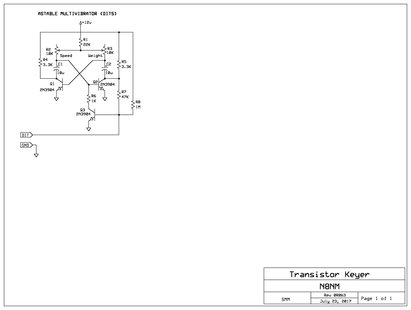
Anyway, might as well start with the easy part: the DIT circuit:


Transistors Q1 and Q2 form the astable multivibrator, which is essentially a free running oscillator that produces square waves by feeding the output of each transistor to the input of the other.  The frequency and duty cycle are determined by C1, C2 and R1, R2 and R3.  By using variable resistors for R2 and R3, we're able to vary the speed and weight (element to space ratio) from the front panel.

When the DIT key is open, transistor Q3 is turned-on through R8, which forces Q2 off by forcing it's base low.  When the key is closed, Q3 is turned off, allowing Q2 to be turned on by Q1 and allowing the multivibrator to multivibrate.

R7's purpose in life is to create the "self-completing" dits by creating something of a "Wire OR" with the key input: If either the key OR the collector of Q2 are LOW, Q3 is turned on.  So, if the key is opened halfway through a dit, Q2 will keep Q3 on until the dit is complete.  Cool stuff, no?

This is what's running on the solderless breadboard pictured earlier - I'll be tweaking the timing resistor values as I move along, but this is a start...

73!

Thursday, July 20, 2017

Knowing Enough to be Dangerous

In my last post, I mentioned that, even though I'm not wild about computers, they do sometimes make for decent tools, so I try to know enough about using them to be dangerous.

Now that I'm "officially" finished with the SR-16 project, I'm working on ideas for the next one, which will be an even more ambitious attempt at a "contest grade" multi-band HF transceiver.

In building the 30m rig, I initially made a bad choice of IF frequency - 13.51 Mhz - which placed the 2nd harmonic of the VFO smack in the middle of the band.  The easy fix was to move the IF to 13.56 so that the harmonic of the VFO fell outside of the band, but that also required additional bandpass filtering to manage the now out-of-band spur.  Moving forward, I'm determined to avoid that by analyzing my choice of frequencies and avoiding those that interact unpleasantly.

This requires repeated calculations, something I hate doing but also something computers are pretty good at.  So, knowing enough to be dangerous, I wrote a little C++ program to crunch the numbers:

#include <iostream>
using namespace std;
int main ()
{
  float lo;
  float lowend;
  float highend;
  float step;
  float rf;
  int harmonic= 1;
  float spur;
  float range;
  int harmonicNumber;
  cout << "Please enter the LOWEST receive/transmit frequency in MHz: ";
  cin >> lowend;
  cout << "Please enter the HIGHEST receive/transmit frequency in MHz: ";
  cin >> highend;
  cout << "Please enter the STEP in MHz ";
  cin >> step;
  cout << "Please enter the IF frequency in MHz: ";
  cin >> rf;
  cout << "Please enter the number of harmonics to extend to ";
  cin >> harmonicNumber;
  cout << "The tuning range you entered is " << lowend <<" to"<<" MHz.\n";
  cout << "The IF you entered is " << rf <<".\n";
  cout << "Analyzing to the " <<harmonicNumber << "th Harmonics... \n";
  for(range = lowend; range <= highend; range = range + step)
  {
    //lo = rf - range; // low side injection
    lo = rf + range; //high side injection
    for(harmonic=1;harmonic <=harmonicNumber;harmonic ++)
    {
        spur = lo * harmonic;
        if ((harmonic > 1) && (spur > (lowend*.9)) && (spur < (highend*1.1)))
        {
            cout<<"Warning!!! When tuned to " << range <<"; the " << harmonic  <<" harmonic of the LO ("<<lo<<") is: " << spur << ".\n";
        }
        spur = rf * harmonic;
        if ((harmonic > 1) && (spur > (lowend * .9)) && (spur < (highend * 1.1)))
        {
            cout<<"Warning!!! When tuned to " << range <<"; the " << harmonic  <<" harmonic of the IF ("<<rf<<") is: " << spur << ".\n";
        }
        spur=lo*harmonic+rf;
        if ((harmonic > 1) && (spur > (lowend*.9)) && (spur < (highend*1.1)))
        {
            cout<<"Warning!!! When tuned to " << range <<"; the " << harmonic  <<" harmonic of the LO ("<<lo<<") + the IF ("<<rf<<") is: " << spur << ".\n";
        }
        spur = lo*harmonic - rf;

       if ((harmonic > 1) && (spur > (lowend*.9)) && (spur < (highend*1.1)))
        {
            if (spur>0)
            {
                cout<<"Warning!!! When tuned to " << range <<"; the "<<harmonic <<" harmonic of the LO ("<<lo<<")- the IF ("<<rf<<") is: "<<spur<<".\n";
            }
        }
        spur=rf*harmonic+lo;
       if ((harmonic > 1) && (spur > (lowend*.9)) && (spur < (highend*1.1)))
        {
            cout<<"Warning!!! When tuned to " << range <<"; the "<<harmonic <<" harmonic of the IF ("<<rf<<") + the LO ("<<lo<<") is: "<<spur<<".\n";
        }
        spur=rf*harmonic-lo;
      if ((harmonic > 1) && (spur > (lowend*.9)) && (spur < (highend*1.1)))
        {
            if (spur>0)
            {
                cout<<"Warning!!! When tuned to " << range <<"; the "<<harmonic <<" harmonic of the IF ("<<rf<<") - the LO ("<<lo<<") is: "<<spur<<".\n";
            }
        }
    }
  }
  main();
  return 0;
}
If this looks like gibberish, here's something that I hope will be encouraging: I'm not a programmer, not terribly bright, and figured out how to do this in a couple of hours.  If I can do it, anyone can!

Anyway, this program runs in the Linux terminal and will prompt you for the low and high ends of the band of interest, how many points within the band to analyse, the IF (BFO) frequency and the number of harmonics that you want the analysis to look at.  Then it crunches the numbers, and displays any "hits" that occur within 10% of the band edges.  If there are no hits, it dumps you back to the beginning (exit with "control-C".)

Here's a screen shot of running an analysis of the 40m band (in 1 Hz increments) and an IF of 6.144 MHz, running out to the 100th harmonics.  This took about 2 seconds for the computer to crunch the numbers and give an "all clear".

Here's one where I chose a bad IF frequency so that it'll show some "hits":


I literally had this written within a couple of hours of writing my first "Hello World" in C++.  It helped that I understood the math and some basic programming concepts, but yeah - this is something anyone can do, so there's no reason to be intimidated by it.

I promise, I'll get back to the Real Radio Stuff in my next post; I just wanted to write this one to show an example of how a computer and **very little** knowledge of programming can be a useful weapon in the homebrewer's arsenal.

73 Steve N8NM


Tuesday, July 11, 2017

SR-16 Arduino Sketch "Module" - Simple Interrupt Service Routine to Generate CW Side Tone.

I'm going to start this post with a proclamation: I am not a programmer.  Truth be told, I'm not all that wild about computers, but, like any other tool, they've got their purpose, so I try to get along with them when it suits me.

I've got some friends for whom the computer is the means and the end - it's the computer itself that provides the entertainment.  Me, not so much, but, being a guy who spends his free time building ham radios in his basement, I don't think it's my place to judge.  Different strokes.

That being said, computers are usually good at doing things that are mind numbingly routine and stupidly boring, and they do them at lightning speed and with consistent results - something I couldn't do if I wanted to. But, enough about my personality quirks, let's get on to the good stuff.

The Arduino has the tone command that Farhan and others (including me) use to generate the CW sidetone that is (after filtering - it's a square wave) sent to the audio chain for monitoring and the balanced modulator for transmission. 
So, in the code, you're monitoring the input connected to your key and, when it's closed, sending a tone to the appropriate output.  Once you've defined the input and output pins, the code to do this is alarmingly simple:

int buttonState = digitalRead(KEY_IN);  // read "KEY_IN", save value in "buttonState"
  if (buttonState==LOW)                         // is the key closed?
    {
      tone(TONE_OUT,750);    }                // if yes, send 750 HZ tone on "TONE_OUT"
    else                                                     // Otherwise
    {
      noTone(TONE_OUT);                      // send no tone on "Tone_OUT"
    }

Looking at the Raduino sketch, I see where Farhan's got similar code already written to accomplish this, but it looks like he never calls it - actually, he's commented out the lines in the loop() that would call this function - and I think I know why:  The transmitted CW would sound like my fist after a few too many visits to the Guinness low-gravity draught head. 

The loop() function executes it's instructions sequentially, over and over until the cows come home.  So, before it gets to the instruction telling it to check and see if the key's closed, it's gotta finish all the prior instructions.  If you have a very short loop(), this is probably OK - the Arduino is pretty speedy.  On the other hand, if you're doing a lot of things in the loop(), it can be a problem.

A better way to do it would be to use a pin change interrupt. Then, the moment that the key input goes from high to low, the Arduino will stop whatever it was doing (loop())  and execute the commands in the interrupt service routine (ISR).

I've been in the habit of avoiding using interrupts because, truth be told, I didn't know how.  Then, I found this website (https://thewanderingengineer.com/2014/08/11/arduino-pin-change-interrupts/). Print it, study it, learn it, it'll change your life; it's certainly changed mine!

Basically, I just followed the three steps outlined in that blog:

Step 1 - Turn on pin change interrupts:

OK, I'm using input D11.  The Arduino data sheet shows that  will be one of    the inputs on "Port B", so I'll turn that on:
PCICR |= 0b00000001;

Step 2 - Choose which pins to interrupt:

Again referring to the data sheet, D11 is Pin 3 on Port B, so I'll create a "mask" so that we only look at that pin:
PCMSK0 |=0b00001000;

Step 3 - Write the ISR:


/***************************************/
/* Interrupt service routine to       */
/* generate CW tone on keydown  */
/* Version 1                                  */
/**************************************/

ISR(PCINT0_vect) {
//Generate CW:
     int buttonState = digitalRead(KEY_IN);
  if (buttonState==LOW)
    {
      tone(TONE_OUT,750);    }
    else
    {
      noTone(TONE_OUT);
    }
}


And, by golly, that's it!  Loaded it into my rig and it works like nobody's business.

Now, if you cut and paste this into your sketch, I guarantee it's not going to work because I've deliberately left out a few things.  I'm silly that way. But, my intent isn't to write a how-to, but to encourage anyone who, like me, was intimidated by the concept of using interrupts to just go out there and grab 'em by the cajones.  Like most things technical, it's not hard to understand once you find an explanation that "clicks" with you.

73 - Steve N8NM